Dell XPS 630i Service Manual - Page 95
Front I/O Panel, Removing the Front I/O Panel
 |
View all Dell XPS 630i manuals
Add to My Manuals
Save this manual to your list of manuals |
Page 95 highlights
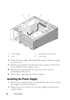
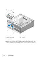
Front I/O Panel Removing the Front I/O Panel CAUTION: Before you begin any of the procedures in this section, follow the safety instructions in the Product Information Guide. 1 Follow the procedures in "Before You Begin" on page 9. 2 Remove the computer cover (see "Removing the Computer Cover" on page 13). 3 Remove any full-length expansion cards (see "Removing PCI and PCI Express Cards" on page 32). NOTICE: Carefully note the routing of each cable before you disconnect it, so that you are sure to re-route cables correctly. An incorrectly routed or a disconnected cable could lead to computer problems. 4 Disconnect the cables from the master I/O board. 5 Remove the card fan cage (see "Removing the Card Fan" on page 69) 6 Disconnect the FRONT_AUDIO_USB_LED cable, the FRONT_USB_LED cable, and the USB_MB cable from the front I/O panel. 7 Remove the drive panel (see "Removing the Drive Panel" on page 53). 8 Remove the front panel: a Release the four tabs that secure the front panel to the chassis. b Carefully, pivot the front panel away from the computer to release it from the chassis. c Disconnect the FRONT_LED cable from the front panel to remove the front panel. Front I/O Panel 95
-
 1
1 -
2
-
3
-
4
-
5
-
6
-
7
-
8
-
9
-
10
-
11
-
12
-
13
-
14
-
15
-
16
-
17
-
18
-
19
-
20
-
21
-
22
-
23
-
24
-
25
-
26
-
27
-
28
-
29
-
30
-
31
-
32
-
33
-
34
-
35
-
36
-
37
-
38
-
39
-
40
-
41
-
42
-
43
-
44
-
45
-
46
-
47
-
48
-
49
-
50
-
51
-
52
-
53
-
54
-
55
-
56
-
57
-
58
-
59
-
60
-
61
-
62
-
63
-
64
-
65
-
66
-
67
-
68
-
69
-
70
-
71
-
72
-
73
-
74
-
75
-
76
-
77
-
78
-
79
-
80
-
81
-
82
-
83
-
84
-
85
-
86
-
87
-
88
-
89
-
 90
90 -
 91
91 -
 92
92 -
 93
93 -
 94
94 -
 95
95 -
 96
96 -
 97
97 -
 98
98 -
 99
99 -
 100
100 -
101
-
102
-
103
-
104
-
105
-
106
-
107
-
108
-
109
-
110
-
111
-
112
-
113
-
114
-
115
-
116
-
117
-
118
-
119
-
120
 |
 |