Dell XPS 630i Service Manual - Page 23
DC Power Connectors P15, Power Button DC Pin Assignments, Black, 12 VDC, Yellow, Green/Yellow, 5 VDC - pc
 |
View all Dell XPS 630i manuals
Add to My Manuals
Save this manual to your list of manuals |
Page 23 highlights
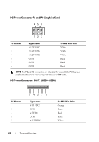
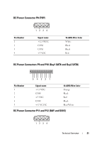
DC Power Connectors P15 5678 1 2 34 Pin Number 1 2 3 4 5 6 7 8 Signal name COM COM COM COM +12 VDC +12 VDC +12 VDC +12 VDC Power Button DC Pin Assignments 16-AWG Wire Color Black Black Black Black Yellow Yellow Green/Yellow Green/Yellow Pin Number 1 2 3 4 5 6 7 8 9 10 Signal name +5 VDC PC LED Hard-drive LED Ground Cable detect PWRBTN NOTE: The PWRBTN signal is inverted. N/A Ground N/A Key Technical Overview 23
-
 1
1 -
2
-
3
-
4
-
5
-
6
-
7
-
8
-
9
-
10
-
11
-
12
-
13
-
14
-
15
-
16
-
17
-
 18
18 -
 19
19 -
 20
20 -
 21
21 -
 22
22 -
 23
23 -
 24
24 -
 25
25 -
 26
26 -
 27
27 -
 28
28 -
29
-
30
-
31
-
32
-
33
-
34
-
35
-
36
-
37
-
38
-
39
-
40
-
41
-
42
-
43
-
44
-
45
-
46
-
47
-
48
-
49
-
50
-
51
-
52
-
53
-
54
-
55
-
56
-
57
-
58
-
59
-
60
-
61
-
62
-
63
-
64
-
65
-
66
-
67
-
68
-
69
-
70
-
71
-
72
-
73
-
74
-
75
-
76
-
77
-
78
-
79
-
80
-
81
-
82
-
83
-
84
-
85
-
86
-
87
-
88
-
89
-
90
-
91
-
92
-
93
-
94
-
95
-
96
-
97
-
98
-
99
-
100
-
101
-
102
-
103
-
104
-
105
-
106
-
107
-
108
-
109
-
110
-
111
-
112
-
113
-
114
-
115
-
116
-
117
-
118
-
119
-
120
 |
 |

Technical Overview
23
DC Power Connectors P15
Power Button DC Pin Assignments
Pin Number
Signal name
16-AWG Wire Color
1
COM
Black
2
COM
Black
3
COM
Black
4
COM
Black
5
+12 VDC
Yellow
6
+12 VDC
Yellow
7
+12 VDC
Green/Yellow
8
+12 VDC
Green/Yellow
Pin Number
Signal name
1
+5 VDC
2
PC LED
3
Hard-drive LED
4
Ground
5
Cable detect
6
PWRBTN
NOTE:
The PWRBTN signal is inverted.
7
N/A
8
Ground
9
N/A
10
Key
4
1
2
3
8
5
6
7