Dell XPS 630i Service Manual - Page 85
to secure the processor., Pivot the socket release lever back toward the socket and snap it into place
 |
View all Dell XPS 630i manuals
Add to My Manuals
Save this manual to your list of manuals |
Page 85 highlights
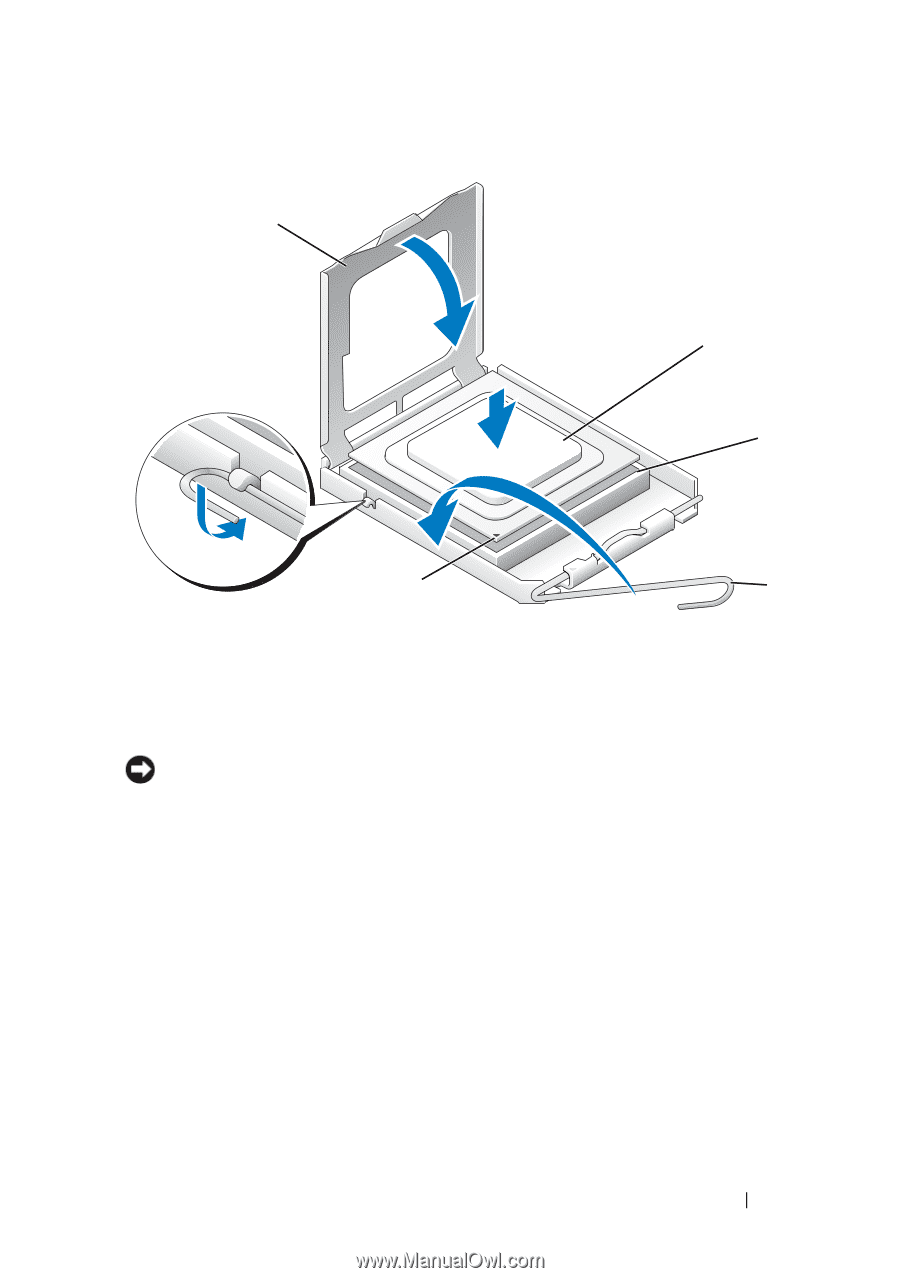
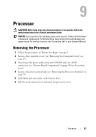
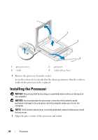
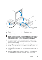
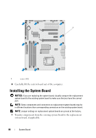
1 2 3 5 4 1 processor cover 3 socket 5 socket pin-1 indicator 2 processor 4 socket release lever NOTICE: Socket pins are delicate. To avoid damage, ensure that the processor is aligned properly with the socket, and do not use excessive force when you install the processor. Be careful not to touch or bend the pins on the system board. 2 Set the processor lightly in the socket and ensure that the processor is aligned in the socket. When the processor is positioned correctly, apply minimal pressure to seat it. 3 When the processor is fully seated in the socket, close the processor cover. 4 Pivot the socket release lever back toward the socket and snap it into place to secure the processor. 5 Replace the processor heatsink (see "Installing the Processor Heatsink" on page 80). 6 Reconnect the power cables to the POWER and 12V_ATXP connectors (see "System Board Components" on page 16) on the system board. Processor 85
-
 1
1 -
2
-
3
-
4
-
5
-
6
-
7
-
8
-
9
-
10
-
11
-
12
-
13
-
14
-
15
-
16
-
17
-
18
-
19
-
20
-
21
-
22
-
23
-
24
-
25
-
26
-
27
-
28
-
29
-
30
-
31
-
32
-
33
-
34
-
35
-
36
-
37
-
38
-
39
-
40
-
41
-
42
-
43
-
44
-
45
-
46
-
47
-
48
-
49
-
50
-
51
-
52
-
53
-
54
-
55
-
56
-
57
-
58
-
59
-
60
-
61
-
62
-
63
-
64
-
65
-
66
-
67
-
68
-
69
-
70
-
71
-
72
-
73
-
74
-
75
-
76
-
77
-
78
-
79
-
 80
80 -
 81
81 -
 82
82 -
 83
83 -
 84
84 -
 85
85 -
 86
86 -
 87
87 -
 88
88 -
 89
89 -
 90
90 -
91
-
92
-
93
-
94
-
95
-
96
-
97
-
98
-
99
-
100
-
101
-
102
-
103
-
104
-
105
-
106
-
107
-
108
-
109
-
110
-
111
-
112
-
113
-
114
-
115
-
116
-
117
-
118
-
119
-
120
 |
 |