Dell XPS 630i Service Manual - Page 28
If you insert the module correctly, the securing clips snap into the cutouts
 |
View all Dell XPS 630i manuals
Add to My Manuals
Save this manual to your list of manuals |
Page 28 highlights
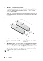
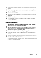
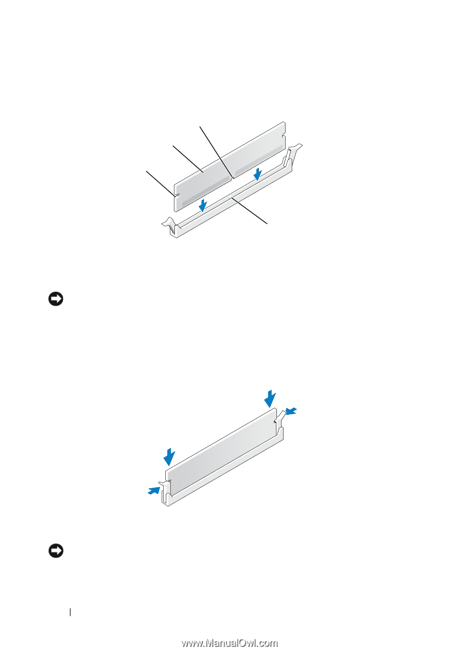
4 Align the notch on the bottom of the module with the crossbar in the connector. 3 2 1 4 1 cutouts (2) 3 notch 2 memory module 4 crossbar NOTICE: To avoid damage to the memory module, press the module straight down into the connector while you apply equal force to each end of the module. 5 Insert the module into the connector until the module snaps into position. If you insert the module correctly, the securing clips snap into the cutouts at each end of the module. 6 Replace the computer cover (see "Replacing the Computer Cover" on page 119). NOTICE: To connect a network cable, first plug the cable into the network port or device and then plug it into the computer. 28 Memory
-
 1
1 -
2
-
3
-
4
-
5
-
6
-
7
-
8
-
9
-
10
-
11
-
12
-
13
-
14
-
15
-
16
-
17
-
18
-
19
-
20
-
21
-
22
-
 23
23 -
 24
24 -
 25
25 -
 26
26 -
 27
27 -
 28
28 -
 29
29 -
 30
30 -
 31
31 -
 32
32 -
 33
33 -
34
-
35
-
36
-
37
-
38
-
39
-
40
-
41
-
42
-
43
-
44
-
45
-
46
-
47
-
48
-
49
-
50
-
51
-
52
-
53
-
54
-
55
-
56
-
57
-
58
-
59
-
60
-
61
-
62
-
63
-
64
-
65
-
66
-
67
-
68
-
69
-
70
-
71
-
72
-
73
-
74
-
75
-
76
-
77
-
78
-
79
-
80
-
81
-
82
-
83
-
84
-
85
-
86
-
87
-
88
-
89
-
90
-
91
-
92
-
93
-
94
-
95
-
96
-
97
-
98
-
99
-
100
-
101
-
102
-
103
-
104
-
105
-
106
-
107
-
108
-
109
-
110
-
111
-
112
-
113
-
114
-
115
-
116
-
117
-
118
-
119
-
120
 |
 |
28
Memory
4
Align the notch on the bottom of the module with the crossbar in the
connector.
NOTICE:
To avoid damage to the memory module, press the module straight down
into the connector while you apply equal force to each end of the module.
5
Insert the module into the connector until the module snaps into position.
If you insert the module correctly, the securing clips snap into the cutouts
at each end of the module.
6
Replace the computer cover (see "Replacing the Computer Cover" on
page 119).
NOTICE:
To connect a network cable, first plug the cable into the network port or
device and then plug it into the computer.
1
cutouts (2)
2
memory module
3
notch
4
crossbar
3
2
1
4