EVGA 132-YW-E179-TR User Guide
EVGA 132-YW-E179-TR Manual
 |
View all EVGA 132-YW-E179-TR manuals
Add to My Manuals
Save this manual to your list of manuals |
EVGA 132-YW-E179-TR manual content summary:
- EVGA 132-YW-E179-TR | User Guide - Page 1
- EVGA 132-YW-E179-TR | User Guide - Page 2
- EVGA 132-YW-E179-TR | User Guide - Page 3
Table of Contents - EVGA 132-YW-E179-TR | User Guide - Page 4
- EVGA 132-YW-E179-TR | User Guide - Page 5
- EVGA 132-YW-E179-TR | User Guide - Page 6
- EVGA 132-YW-E179-TR | User Guide - Page 7
List of Figures - EVGA 132-YW-E179-TR | User Guide - Page 8
hardware necessary to install and connect your new EVGA nForce® 790i SLI FTW motherboard. However, it does not contain the following items that must be purchased separately to make the motherboard functional. Intel Microprocessor System Memory Cooling fan for the Microprocessor Graphics Card - EVGA 132-YW-E179-TR | User Guide - Page 9
you for purchasing the EVGA nForce 790i SLI FTW Motherboard. This motherboard offers the tools, performance, and overclocking potential that PC Enthusiasts demand. When combined with two or three SLI-Ready NVIDIA GeForce graphics cards, you get innovative NVIDIA SLI Technology for enhanced visual - EVGA 132-YW-E179-TR | User Guide - Page 10
GB/sec concurrent) bandwidth Low power consumption and power management features Green Function Supports ACPI (Advanced Configuration and Power Interface) Supports S0 (normal), S1 (power on suspend), S3 (suspend to RAM), S4 (Suspend to disk - depends on OS), and S5 (soft - off) Expansion - EVGA 132-YW-E179-TR | User Guide - Page 11
following equipment is included in the EVGA nForce 790i SLI FTW motherboard box. EVGA nForce 790i SLI FTW Motherboard This PCI Express motherboard contains the NVIDIA nForce 790i SLI SPP and MCP and is SLI-ready. 1 - Visual guide Helps to visually guide you through the hardware installation of the - EVGA 132-YW-E179-TR | User Guide - Page 12
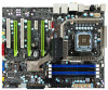
Graphics Cards 1 - 3-Way SLI Bridge Allows for a 3-Way SLI set up with compatible NVIDA GeForce Graphics Cards The EVGA nForce 790i SLI FTW motherboard with the NVIDIA nForce 790i SLI SPP and MCP processors is a PCI Express, SLI-ready motherboard. Figure 1 shows the motherboard and Figures 2 shows - EVGA 132-YW-E179-TR | User Guide - Page 13
10 9 8 11 7 6 5 28 1 2 3 4 1. CPU Socket - For Intel LGA 775 CPUs 2. nForce 790i SLI SPP with Active Cooling - Also known as the Northbridge 3. CPU fan connector - Connect CPU Fan Motherboard CMOS Battery - Helps retain system BIOS settings Figure 1. EVGA nForce 790i SLI FTW Motherboard Layout - EVGA 132-YW-E179-TR | User Guide - Page 14
1 7 9 9 2 3 4 5 6 8 1. PS/2 Mouse Port 2. PS/2 Keyboard Port 3. Coaxial SPDIF output 4. Optical SPDIF output 5. eSATA port 6. USB 2.0 ports (Six) 7. 8. Audio Port Blue Green Pink Orange Black Grey 2-Channel Line-In Line-Out Mic In 6-Channel Line-In Front Speaker Out Mic In Center/ - EVGA 132-YW-E179-TR | User Guide - Page 15
This section will guide you through the installation of the motherboard. The topics covered in this section are: Preparing the motherboard Installing the CPU Installing the CPU fan Installing the memory Installing the motherboard Connecting cables and setting switches To reduce the risk - EVGA 132-YW-E179-TR | User Guide - Page 16
the processor only by the edges and do not touch the bottom of the processor. Use the following procedure to install the CPU onto the motherboard. Unhook the socket lever by pushing down and away from the socket. Lift the load plate. There is a protective socket cover on the load plate - EVGA 132-YW-E179-TR | User Guide - Page 17
types that can be used with this motherboard. Follow the instruction that came with you fan assembly. Be sure that the fan orientation is correct for your chassis type and your fan assembly. Your new motherboard has four 240-pin slots for DDR3 memory. These slots support 256 MB, 512 MB, 1 GB, and - EVGA 132-YW-E179-TR | User Guide - Page 18
a DIMM slot by pressing the module clips outward. Align the memory module to the DIMM slot and insert the module vertically while applying the CPU Fan assembly is aligned with the vents on the covers. The motherboard kit comes with an I/O shield that is used to block radio frequency transmissions - EVGA 132-YW-E179-TR | User Guide - Page 19
the studs/spacers. Align the connectors to the I/O shield. Ensure that the fan assembly is aligned with the chassis vents according to the fan assembly instruction. Secure the motherboard with a minimum of eight-to-ten screws. This section takes you through all the connections necessary on the - EVGA 132-YW-E179-TR | User Guide - Page 20
slots CMOS Clear Button See Figure 1 on page 5 to locate the connectors and button referenced in the following procedure. To support 3-way SLI, this motherboard has the following specific power supply requirements: Minimum 1000 W peak power Six PCI-E power connectors configured in either of - EVGA 132-YW-E179-TR | User Guide - Page 21
and pins are properly aligned with the connector on the motherboard. Firmly plug the power supply cable into the connector and Plug power cable from power supply to PWR1 Board edge Figure 4. PWR1 Motherboard Connector Table 1. PWR1 Pin Assignments Connector Pin Signal 1 +3.3V 24 13 - EVGA 132-YW-E179-TR | User Guide - Page 22
and press firmly until seated. Backpanel connector edge 8 5 4 1 The IDE connector supports Ultra ATA 133/100/66 IDE hard disk drives. Connect the blue connector (the cable end with a single connector) to the motherboard. Connect the black connector (the cable with two closely spaced black and - EVGA 132-YW-E179-TR | User Guide - Page 23
The Serial ATA connector is used to connect a Serial ATA I or Serial ATA II device to the motherboard. These connectors support the thin Serial ATA cables for primary storage devices. The current Serial ATA II interface allows up to 300MB/s data transfer rate. There are ten - EVGA 132-YW-E179-TR | User Guide - Page 24
The front panel header on this motherboard is used to connect the following four cables. (see Table 2 for pin definitions): PWRLED Attach the front panel power LED cable to these two pins - EVGA 132-YW-E179-TR | User Guide - Page 25
the bracket to the rear panel of your chassis. Connect the end of the cable to the IEEE 1394a connector on the motherboard. Table 3. IEEE 1394a Connector Pins Connector IEEE 1394a Connector 10 9 8 7 6 5 4 3 2 1 Pin 1 2 3 4 5 6 7 8 9 10 Signal TPA+ TPAGND GND TPB+ TPB+12V +12V Empty GND - EVGA 132-YW-E179-TR | User Guide - Page 26
the bracket to the rear panel of your chassis. Connect the two ends of the cables to the USB 2.0 headers on the motherboard. Table 4. USB 2.0 Header Pins Connector USB 2.0 Header Connector Pin 1 3 5 7 9 Pin 2 4 6 8 10 Signal 5V_DUAL DataData+ GND Empty Signal 5V_DUAL DataData+ GND No Connect - EVGA 132-YW-E179-TR | User Guide - Page 27
uses the AC97 standard and provides two kinds of audio output choices: Front Audio and Rear Audio. The front Audio supports retasking function. Table 5. Front Audio Connector Connector Front Audio Connector 10 9 8 7 6 5 4 3 2 1 Pin Signal 1 PORT1_L 2 AUD_GND 3 PORT1_R 4 PRECENCE_J - EVGA 132-YW-E179-TR | User Guide - Page 28
The HD Audio connection supports HD audio standard. Use this if the case does not use the AC97 connectors. Table 6. HD Audio Connector Connector HD audio Connector Pin Signal 1 BCLK 2 - EVGA 132-YW-E179-TR | User Guide - Page 29
The SPDIF header is used to connect to an NVIDIA graphics card for HDMI audio. Connector SPDIF Audio Connector Pin 1 2 3 4 5 6 Signal Power No Pin SPDIF SPDIFI GROUND GROUND - EVGA 132-YW-E179-TR | User Guide - Page 30
There are seven fan connections on this motherboard. The fan speed can be detected and viewed in the section of the CMOS Setup be either a 3-pin or a 4-pin connector. Connect a 3-pin connector to pins 1, 2, and 3 on the motherboard connector. CPU Fan CPU Fan Connector 4 3 2 GN1D SENSE PWR CONTROL - EVGA 132-YW-E179-TR | User Guide - Page 31
System fan connector Fan Connector 3 2 1 GND +12V SENSE Chassis fan connector Chassis fan connector The motherboard kit provides a serial COM port bracket for your system. Connect one side of the cable to the header and then attach the serial COM device to the other side of the cable. - EVGA 132-YW-E179-TR | User Guide - Page 32
The motherboard supports a standard 360K, 720K, 1.2M, 1.44m, and a 2.88M floppy disk drive (FDD). The EVGA nForce 790i SLI FTW motherboard contains seven expansion slots, five PCI Express slots and two PCI slots. 1 2 3 4 5 6 5 - PCI slot 1 - PCIe x16 slot 2 - PCI slot 2 - PCIe x16 slot 3 - - EVGA 132-YW-E179-TR | User Guide - Page 33
The two PCI slots support many expansion cards such as a LAN card, USB card, SCSI card of the x16 slot is up to 4GB/sec (8GB/sec concurrent). The motherboard supports three PCI-Express graphics cards using NVIDIA's SLI technology. When installing a PCI Express x16 card, be sure the retention clip - EVGA 132-YW-E179-TR | User Guide - Page 34
buttons include RESET, POWER and Clear CMOS. Easily turn on/off the system, and conveniently clear the CMOS. The motherboard uses the CMOS ROM to store all the set parameters in the bios. The CMOS can be cleared by using the following procedure: Turn off the AC power supply. Press and hold - EVGA 132-YW-E179-TR | User Guide - Page 35
Provides a two-digit POST code to allow for quick and easy debugging. Debug LED Theses LEDs indicate the system status. POWER LED (Green): When the system is powered on, the LED is on. DIMM LED (Yellow): When the memory slot has power, the LED is on. STANDBY LED (Blue): When the system is - EVGA 132-YW-E179-TR | User Guide - Page 36
are also provided. This section includes the following information: Enter BIOS Setup Main Menu Standard CMOS Features Advanced BIOS Features Advanced Chipset Features Integrated Peripherals Power Management Setup PnP/PCI Configurations PC Health Status Frequency/Voltage - EVGA 132-YW-E179-TR | User Guide - Page 37
the arrow keys to position the selector in the option you choose. To go back to the previous menu, press Esc. Note that on the BIOS screens all data in white is for information only, data in yellow is changeable, data in blue is non-changeable, and data in a red box - EVGA 132-YW-E179-TR | User Guide - Page 38
Saving Select Item Time, Date, Hard Disk Type.., Figure 5. BIOS CMOS Setup Utility Main Menu Standard CMOS Features Use this menu Features Use this menu to optimize system performance and configure clocks, voltages, memory timings, and more. Integrated Peripherals Use this menu to set up - EVGA 132-YW-E179-TR | User Guide - Page 39
Optimized defaults system settings. Set Supervisor Password/Set User Password Use this command to set, change, and disable the password used to access the BIOS menu. Save & Exit Setup Use this command to save settings to CMOS and exit setup. Exit Without Saving Use this command to abandon all - EVGA 132-YW-E179-TR | User Guide - Page 40
: 48: 23 Item Help IDE Channel 0 Master IDE Channel 0 Slave SATA 1 (A0) SATA 2 (A1) SATA 3 (B0) SATA 4 (B1) SATA 5 (C0) SATA 6 (C1) Drive A Halt On Base Memory Extended Memory Total Memory [None] [None] [None] [None] [None] [None] [None] [None] [1.44, 3.5 in.] [All , But Keyboard - EVGA 132-YW-E179-TR | User Guide - Page 41
. IDE Channel 0 Master IDE Channel 0 Slave SATA 1 (A0) SATA 2 (A1) SATA 3 (B0) SATA 4 (B1) SATA 5 (C0) SATA 6 (C1) [None] [None] [None] [None] [None Mode Capacity Cylinder Head Precomp Landing Zone Sector [Press Enter] [Manual} [CHS] 0 MB [ 0] [ 0] [ 0] [ 0] [ 0] Capacity 0 - EVGA 132-YW-E179-TR | User Guide - Page 42
Enter] IDE Channel 0 Slave Access Mode Capacity Cylinder Head Precomp Landing Zone Sector [Manual} [CHS] 0 MB .....0 [ 0] [ 0] [ 0] [ 0] Press ENTER to display sub-menu or enter number manually Cylinder The BIOS supports the following HDD Access Modes: CHS Min= 0 Max=65535 Key in a DEC number - EVGA 132-YW-E179-TR | User Guide - Page 43
to the Standard CMOS Features menu. Drive A Halt On [1.44, 3.5 in.] [All , But Keyboard] Press ENTER to display sub-menu All Errors Whenever the BIOS detects a nonfatal error, the system stops and prompts you. No Errors System boot does not stop for any detected errors. Halt On All Errors - EVGA 132-YW-E179-TR | User Guide - Page 44
POST (Power-On Self Test). Base Memory 640K Base Memory BIOS POST determines the Extended Memory Total Memory 1047552K 1048576K amount of base (or conventional) memory installed in the system. Extended Memory BIOS determines how much extended memory is present during the POST. Total - EVGA 132-YW-E179-TR | User Guide - Page 45
to display the sub-menus. Phoenix - AwardBIOS CMOS Setup Utility Advanced BIOS Features Hard Disk Boot Priority CD-ROM Boot Priority F5:Previous Values F6:Fail-Safe Defaults F7:Optimized Defaults Figure 7. Advanced BIOS Features Menu Note that all data in white is for information only, data - EVGA 132-YW-E179-TR | User Guide - Page 46
Use this option to select the priority for HDD startup. Press Enter to see the list of bootable devices in your system. Use the arrow keys to go to the various devices. Then use the + or - keys to move the device priority up or down in the list. To go back to the previous menu, press Esc. 1. Ch0 - EVGA 132-YW-E179-TR | User Guide - Page 47
Enabling this option allows the system to skip certain test while booting, which reduces the time needed to boot the system. Use the Page Up and Page Down keys to toggle between Enable and Disable. Use this option to set the priority sequence of the devices booted at power on. Use the Page Up and - EVGA 132-YW-E179-TR | User Guide - Page 48
disable this option, you also disable the MPS Version Control for OS option. Use this function to select the Multi-Processor Specification (MPS) version that BIOS passes to the operating system. Use the Page Up and Page Down keys to scroll through the options. This option allows you to enable or - EVGA 132-YW-E179-TR | User Guide - Page 49
Previous Values F6:Fail-Safe Defaults F7:Optimized Defaults Figure 8. Advanced Chipset Features This function allows you to enable or disable caching the system BIOS. This function allows you to enable or disable the High Precision Even Timer (HPET). When Enabled, HPET is used as the timing hardware - EVGA 132-YW-E179-TR | User Guide - Page 50
Select Integrated Peripherals from the CMOS Setup Utility menu and press Enter to display the Integrated Peripherals menu. Phoenix - AwardBIOS CMOS Setup Utility Integrated Peripherals IDE Function Setup RAID Config USB Config MAC Config IEEE 1394 Controller JMicron AHCI (SATA 7/8) JMicron - EVGA 132-YW-E179-TR | User Guide - Page 51
Press Enter to display the IDE Function Setup menu. OnChip IDE Channel0 Primary Master PIO Primary Slave PIO Primary Master UDMA Primary Slave UDMA IDE DMA transfer access Serial-ATA Controller IDE Prefetch Mode IDE HDD Block Mode [Enabled] [Auto] [Auto] [Auto] [Auto] [Enabled] [All Enabled] [ - EVGA 132-YW-E179-TR | User Guide - Page 52
of block read/writes per sector the drive can support. Select [Disabled] if your drive does not support block mode. Press Enter to display the RAID Config menu. RAID Enable SATA 1 (A0) RAID SATA 2 (A1) RAID SATA 3 (B0) RAID SATA 4 (B1) RAID SATA 5 (C0) RAID SATA 6 (C1) RAID [Enabled] [Disabled - EVGA 132-YW-E179-TR | User Guide - Page 53
these function to enable or disable the onchip USB support of the keyboard and/or mouse. Press Enter to display the MAC Config menu. MAC0 LAN MAC1 LAN [Auto] [Auto] MACx LAN Use these functions - EVGA 132-YW-E179-TR | User Guide - Page 54
Select Power Management Setup from the CMOS Setup Utility menu and press Enter to display the Power Management Setup menu. Phoenix - AwardBIOS CMOS Setup Utility Power Management Setup ACPI function APCI Suspend Type Soft-Off by PBTN WOL(PME#) From Soft-Off WOR(RI#) From Soft-Off PWRON After PWR- - EVGA 132-YW-E179-TR | User Guide - Page 55
to enable or disable the Power-on by alarm function. Set to [Disable] to prevent power-on by alarm. When set to [Enable], you can manually put in the day of the month and the time of the alarm. Power-on by Alarm Day of Month Alarm Time (hh:mm:ss - EVGA 132-YW-E179-TR | User Guide - Page 56
This function on the Power Management Setup menu allows you to define the power-on function. Options for this function are: BUTTON ONLY Keyboard 98 Password When [Password] is selected, the KB Power ON Password function is enabled so that you must enter a password. POWER ON Function KB - EVGA 132-YW-E179-TR | User Guide - Page 57
Select PnP/PCI Configuration from the CMOS Setup Utility menu and press Enter to display the PnP/PCI Configuration menu. Phoenix - AwardBIOS CMOS Setup Utility PnP/PCI Configuration Init Display First [PCI Slot] Item Help Resources Controlled By x IRQ Resources [Auto(ESCD)] Press Enter Main - EVGA 132-YW-E179-TR | User Guide - Page 58
or if you can manually select IRQ, DMA, and memory base address fields. Select [Auto(ESCD)] if you want the BIOS to automatically populate these fields. If you select [Manual] so you can architecture. This item is designed to overcome problems that may be caused by some nonstandard VGA cards.. - EVGA 132-YW-E179-TR | User Guide - Page 59
This item controls how long each PCI device can hold the bus before another takes over. When set to higher values, every PCI device can conduct transactions for a longer time and thus improve the effective PCI bandwidth. For better PCI performance, you should set the item to higher values. The - EVGA 132-YW-E179-TR | User Guide - Page 60
Utility PC Health Status Dynamic Fan Control CPU Board MCP55 [Press Enter] 38ºC/ 100ºF 42ºC/ 108ºF 59ºC/ 138ºF Item Help Main Level CPU Core +5V Memory nForce SPP +3.3V +12V +Vbat 1.27V 4.97V 1.48V 1.31V 3.21V 11.91V 3.02V CPU Fan Speed Chassis Fan Speed Chassis Fan2 Speed Aux Fan Speed - EVGA 132-YW-E179-TR | User Guide - Page 61
fans on the motherboard. Set CPU fan speed to [SmartFan] when you want the speed of the fans automatically controlled based on temperature. To set the fan speed to a constant rate, select [Manual] and then enter the speed from 0% to 100%. Set the desired speed for the Aux, nForce, and Chassis fans - EVGA 132-YW-E179-TR | User Guide - Page 62
press Enter to display the Frequency/Voltage Control menu. Phoenix - AwardBIOS CMOS Setup Utility Frequency/Voltage Control System Clocks FSB & Memory Config CPU Feature System Voltages [Press Enter] [Press Enter] [Press Enter] [Press Enter] Item Help Main Level Load timing/voltage - EVGA 132-YW-E179-TR | User Guide - Page 63
that in Figure 9, all of the options are listed. On the actual BIOS screen, you will need to scroll down to see all the options. SPPMCP Ref Clock, MHz [Auto] 100 **HT Multiplier** nForce SPP --> nForce MCP [5 x] nForce SPP - EVGA 132-YW-E179-TR | User Guide - Page 64
be changed by the user). To change the SLI-Ready memory, FSB memory, and memory timing, go to the FSB & Memory screen. CPU Multiplier This value changes the chip to the MCP chip. Values are [1 x] through [5 x]. nForce MCP - EVGA 132-YW-E179-TR | User Guide - Page 65
CPU Spread Spectrum This option reduces the EMI generated by the CPU. Options are [Disabled] and [Center Spread]. HT Spread Spectrum This option reduces the EMI generated by the HT. Options are [Disabled] and [Auto]. PCIe Spread Spectrum (SPP) This option reduces the EMI generated by the SPP - EVGA 132-YW-E179-TR | User Guide - Page 66
Timing Setting [Press Enter] Main Level "Auto" realizes the complete optimized memory settings when EPP 2.0 memory is installed Optimized memory settings by allowing X% CPU overclocking CPU overclocking may require manual overvoltaging of the CPU to improve system stability Move Enter:Select - EVGA 132-YW-E179-TR | User Guide - Page 67
), MHz and MEM (DDR), MHz are changed to editable and the FSB and memory speeds can be entered manually. As the FSB speed is changed, CPU Freq, MHz changes proportionally. FSB - Memory Clock Mode [Unlinked] x FSB - Memory Ratio Auto FSB (QDR), MHz [1067] Actual FSB (QDR), MHz 1066.7 MEM (DDR - EVGA 132-YW-E179-TR | User Guide - Page 68
Timing Setting menu. Use this menu to set optimal timings or to manually enter timings. Phoenix - AwardBIOS CMOS Setup Utility Memory Timing Setting Parameters Settings Current Value Item Help Memory Timing Setting [Optimal] x tCL (CAS Latency) Auto(7) x tRCD Auto(7) x tRP Auto(7) x tRAS - EVGA 132-YW-E179-TR | User Guide - Page 69
to select Expert. When Expert is selected, all timing categories are enabled for manual input. Note that you should set the value to Optimal to use the manufacturers' recommended values. Parameters Settings Current Value Memory Timing Setting tCL (CAS Latency) tRCD tRP tRAS Command Per Clock (CMD - EVGA 132-YW-E179-TR | User Guide - Page 70
tRFC: Minimum Refresh Recover Time Delay (options are Auto, 90ns, 110ns,160ns and 285nS). Select CPU Feature from the Frequency/Voltage Control menu and press Enter to display the CPU Feature menu. Phoenix - AwardBIOS CMOS Setup Utility CPU Feature Limit CPUID MaxVal Intel SpeedStep x PPM Mode - EVGA 132-YW-E179-TR | User Guide - Page 71
by reducing the CPU multiplier and CPU core voltage. TM1 & TM2 Enables support for both TM1 and TM2. C1E Enhanced Halt State When set to enabled, this CPU is idle. Idle occurs when the operating system issues a halt instruction. Execute Disable Bit When this function is disabled, it forces the XD - EVGA 132-YW-E179-TR | User Guide - Page 72
may be damaged. Overclocking may Void your warranty. Move Enter:Select +/-/PU/PD:Value F10:Save ESC:Exit F1:General Help F5:Previous Values F6:Fail-Safe Defaults F7:Optimized Defaults Figure 17. System Voltages Menu EVGA VDroop control EVGA VDroop control is a safety measure by motherboards to - EVGA 132-YW-E179-TR | User Guide - Page 73
[Auto] to automatically set the voltage level for the CPU FSB. Memory This function defines the voltage level for the DRAM. Use the Page Up [Auto] to automatically set the voltage. nForce SPP This function defines the core voltage level for the NVIDIA nForce SPP chip. Use the Page Up and Page - EVGA 132-YW-E179-TR | User Guide - Page 74
This function loads the system voltages and timing settings that were defined in the System Voltages menu. You can set up to three profile settings using the Save timing/voltage set function. There are three profile options that can be loaded. The default setting is Auto for all settings. Press - EVGA 132-YW-E179-TR | User Guide - Page 75
CD that has been shipped with your EVGA motherboard contains the following software and drivers: Motherboard Drivers Audio Drivers SATA Controller Drivers Create a RAID Floppy Disk Adobe Acrobat Reader® View CD Manual Insert the EVGA nForce 790i SLI FTW installation CD in the the system - EVGA 132-YW-E179-TR | User Guide - Page 76
Programmable Interrupt Controller BIOS - Basic Input Output System CD-ROM - Compact Disc Read-Only Memory CMOS - Complementary In-line Memory Module DRAM - Dynamic random access memory DVD - Digital Versatile Disc DVI - Digital Video Interface FDC - Floppy Disk Controller FSB - Front Side Bus FTW - - EVGA 132-YW-E179-TR | User Guide - Page 77
LGA - Land Grid Array LN2 - Liquid Nitrogen Cooling MAC - Media Access Control MCP - Media and Computer System Interface SFR - Split Frame Rendering SLI - Scalable Link Interface SPD - Serial Presence Detect SPDIF - Sony/Philips Digital Interconnect Format SPP - System Platform Processors TCP - EVGA 132-YW-E179-TR | User Guide - Page 78
This section provides the Award POST Codes (Table 6) for the EVGA nForce 790i SLI FTW Motherboard during system boot up. These POST Codes are displayed on the LED POST Code readout located directly onboard the motherboard. Only (Table 6) Codes will display on the LED POST Code readout. Table 6. - EVGA 132-YW-E179-TR | User Guide - Page 79
1C 1D 1E 1F 20 21 22 23 24 25 Name Reserved Award POST Codes Description Reserved CheckSum Check Check the integrity of the ROM,BIOS and message Reserved Autodetect EEPROM Check Flash type and copy flash write/erase routines Reserved Test CMOS Test and Reset CMOS Reserved Load Chipset - EVGA 132-YW-E179-TR | User Guide - Page 80
8259-1 Mask Reserved Test 8259-2 Award POST Codes Description Init onboard clock generator and sensor Setup BIOS DATA AREA (BDA) Chipset programming and CPU Speed detect Initialize Video Test Video Memory and display Logos Early Keyboard Reset Test DMA channel 0 Test DMA channel 1 Test DMA Page - EVGA 132-YW-E179-TR | User Guide - Page 81
Reserved 4E Init APIC 4F Reserved 50 USB init 51 Reserved 52 Memory Test 53 Reserved 54 Reserved 55 CPU display 56 Reserved 57 PnP interrupt occurred. Reinitialize Preboot agent serial port If EISA non-volatile memory checksum is good, execute EISA initialization. If not, execute ISA tests and clear - EVGA 132-YW-E179-TR | User Guide - Page 82
PS2 Mouse port ACPI sub-system initializing Initialize cache controller Enter setup check and autoconfiguration check up Initialize floppy disk drive Install FDD and setup BIOS data area parameters Initialize hard drive controller - EVGA 132-YW-E179-TR | User Guide - Page 83
. HDD check for write protection Check POST error and display them and ask for user intervention Ask password security. Write all CMOS values back to RAM and clear screen. Display PNP devices Final USB initialization Setup ACPI tables Scan for Option ROMs Enable Parity Check - EVGA 132-YW-E179-TR | User Guide - Page 84
93 94 95 96 C0 C1 C2 C3 C4 C5 C6 CF B0 B1 BF E1-EF FF Name Reserved IRQ12 Enable Reserved Reserved Reserved Boot Medium Read Final Init NumLock Boot Attempt Base CPU test Memory Presence Early Memory Extend Memory Special Display Early Shadow Cache presence CMOS Check Spurious Unclaimed NMI Program
-
 1
1 -
 2
2 -
 3
3 -
 4
4 -
 5
5 -
 6
6 -
 7
7 -
8
-
9
-
10
-
11
-
12
-
13
-
14
-
15
-
16
-
17
-
18
-
19
-
20
-
21
-
22
-
23
-
24
-
25
-
26
-
27
-
28
-
29
-
30
-
31
-
32
-
33
-
34
-
35
-
36
-
37
-
38
-
39
-
40
-
41
-
42
-
43
-
44
-
45
-
46
-
47
-
48
-
49
-
50
-
51
-
52
-
53
-
54
-
55
-
56
-
57
-
58
-
59
-
60
-
61
-
62
-
63
-
64
-
65
-
66
-
67
-
68
-
69
-
70
-
71
-
72
-
73
-
74
-
75
-
76
-
77
-
78
-
79
-
80
-
81
-
82
-
83
-
84
 |
 |
