EVGA 132-YW-E179-TR User Guide - Page 20
Power Supply Connectors
 |
View all EVGA 132-YW-E179-TR manuals
Add to My Manuals
Save this manual to your list of manuals |
Page 20 highlights
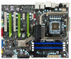
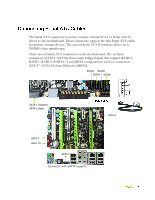
Serial ATA II Chassis Fans Rear panel USB 2.0 Adapter Expansion slots CMOS Clear Button See Figure 1 on page 5 to locate the connectors and button referenced in the following procedure. To support 3-way SLI, this motherboard has the following specific power supply requirements: Minimum 1000 W peak power Six PCI-E power connectors configured in either of the following configurations (see Figure 3): Three 6-pin (3x2) and three 8-pin (4x2) PCI-E power connectors or Six 6-pin (3x2) PCI-E power connectors 8-pin (4x2) PCI-E Connector 6-pin (3x2) PCI-E connector Figure 3. Power Supply Connectors
-
 1
1 -
2
-
3
-
4
-
5
-
6
-
7
-
8
-
9
-
10
-
11
-
12
-
13
-
14
-
 15
15 -
 16
16 -
 17
17 -
 18
18 -
 19
19 -
 20
20 -
 21
21 -
 22
22 -
 23
23 -
 24
24 -
 25
25 -
26
-
27
-
28
-
29
-
30
-
31
-
32
-
33
-
34
-
35
-
36
-
37
-
38
-
39
-
40
-
41
-
42
-
43
-
44
-
45
-
46
-
47
-
48
-
49
-
50
-
51
-
52
-
53
-
54
-
55
-
56
-
57
-
58
-
59
-
60
-
61
-
62
-
63
-
64
-
65
-
66
-
67
-
68
-
69
-
70
-
71
-
72
-
73
-
74
-
75
-
76
-
77
-
78
-
79
-
80
-
81
-
82
-
83
-
84
 |
 |
Serial ATA II
Chassis Fans
Rear panel USB 2.0 Adapter
Expansion slots
CMOS Clear Button
See Figure 1 on page 5 to locate the connectors and button referenced in the
following procedure.
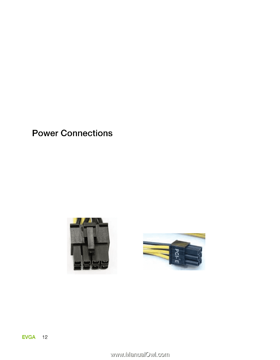
To support 3-way SLI, this motherboard has the following specific power supply
requirements:
Minimum 1000 W peak power
Six PCI-E power connectors configured in either of the following
configurations (see Figure 3):
Three 6-pin (3x2) and three 8-pin (4x2) PCI-E power connectors
or
Six 6-pin (3x2) PCI-E power connectors
8-pin (4x2) PCI-E Connector
6-pin (3x2) PCI-E connector
Figure 3.
Power Supply Connectors