EVGA 132-YW-E179-TR User Guide - Page 21
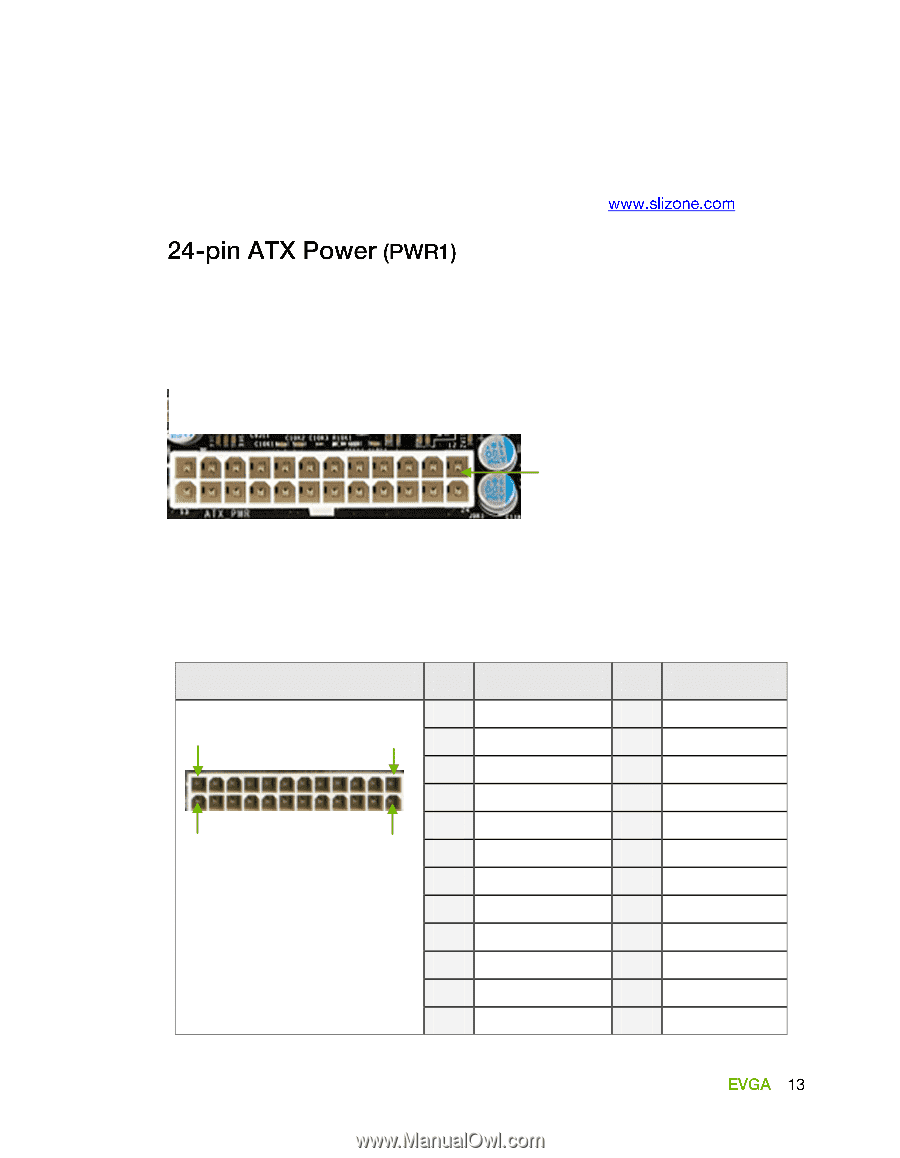
PWR1 Motherboard Connector, Table 1., PWR1 Pin Assignments
 |
View all EVGA 132-YW-E179-TR manuals
Add to My Manuals
Save this manual to your list of manuals |
Page 21 highlights
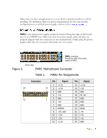
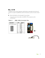
Make sure you have enough power to cover all the expansion cards you will be installing. To determine what you power requirements are for your specific configuration or a certified power supply vendor, refer to . PWR1 is the main power supply connector located along the edge of the board next to the DIMM slots. Make sure that the power supply cable and pins are properly aligned with the connector on the motherboard. Firmly plug the power supply cable into the connector and make sure it is secure. PWR1 connector Plug power cable from power supply to PWR1 Board edge Figure 4. PWR1 Motherboard Connector Table 1. PWR1 Pin Assignments Connector Pin Signal 1 +3.3V 24 13 2 +3.3V 3 GND 4 +5V 5 GND 12 1 6 +5V 7 GND 8 PWROK 9 +5V_AUX 10 +12V 11 +12V 12 +3.3V Pin Signal 13 +3.3V 14 -12V 15 GND 16 PS_ON 17 GND 18 GND 19 GND 20 RSVD 21 +5V 22 +5V 23 +5V 24 GND
-
 1
1 -
2
-
3
-
4
-
5
-
6
-
7
-
8
-
9
-
10
-
11
-
12
-
13
-
14
-
15
-
 16
16 -
 17
17 -
 18
18 -
 19
19 -
 20
20 -
 21
21 -
 22
22 -
 23
23 -
 24
24 -
 25
25 -
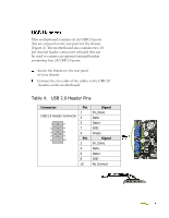 26
26 -
27
-
28
-
29
-
30
-
31
-
32
-
33
-
34
-
35
-
36
-
37
-
38
-
39
-
40
-
41
-
42
-
43
-
44
-
45
-
46
-
47
-
48
-
49
-
50
-
51
-
52
-
53
-
54
-
55
-
56
-
57
-
58
-
59
-
60
-
61
-
62
-
63
-
64
-
65
-
66
-
67
-
68
-
69
-
70
-
71
-
72
-
73
-
74
-
75
-
76
-
77
-
78
-
79
-
80
-
81
-
82
-
83
-
84
 |
 |