EVGA 132-YW-E179-TR User Guide - Page 26
Table 4., USB 2.0 Header Pins
 |
View all EVGA 132-YW-E179-TR manuals
Add to My Manuals
Save this manual to your list of manuals |
Page 26 highlights
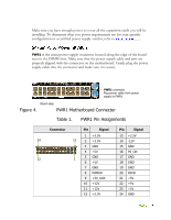
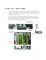
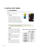
This motherboard contains six (6) USB 2.0 ports that are exposed on the rear panel of the chassis (Figure 2). The motherboard also contains two 10pin internal header connectors onboard that can be used to connect an optional external bracket containing four (4) USB 2.0 ports. Secure the bracket to the rear panel of your chassis. Connect the two ends of the cables to the USB 2.0 headers on the motherboard. Table 4. USB 2.0 Header Pins Connector USB 2.0 Header Connector Pin 1 3 5 7 9 Pin 2 4 6 8 10 Signal 5V_DUAL DataData+ GND Empty Signal 5V_DUAL DataData+ GND No Connect
-
 1
1 -
2
-
3
-
4
-
5
-
6
-
7
-
8
-
9
-
10
-
11
-
12
-
13
-
14
-
15
-
16
-
17
-
18
-
19
-
20
-
 21
21 -
 22
22 -
 23
23 -
 24
24 -
 25
25 -
 26
26 -
 27
27 -
 28
28 -
 29
29 -
 30
30 -
 31
31 -
32
-
33
-
34
-
35
-
36
-
37
-
38
-
39
-
40
-
41
-
42
-
43
-
44
-
45
-
46
-
47
-
48
-
49
-
50
-
51
-
52
-
53
-
54
-
55
-
56
-
57
-
58
-
59
-
60
-
61
-
62
-
63
-
64
-
65
-
66
-
67
-
68
-
69
-
70
-
71
-
72
-
73
-
74
-
75
-
76
-
77
-
78
-
79
-
80
-
81
-
82
-
83
-
84
 |
 |
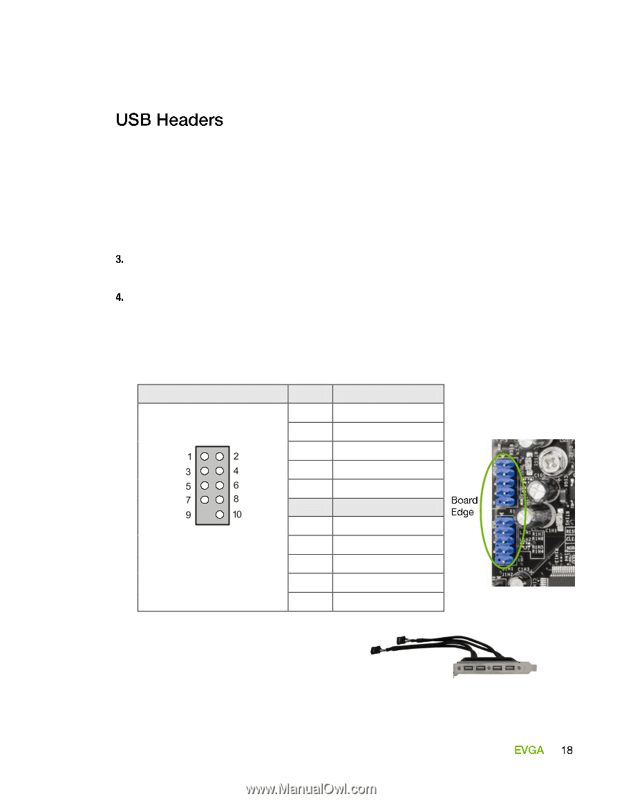
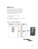
This motherboard contains six (6) USB 2.0 ports
that are exposed on the rear panel of the chassis
(Figure 2). The motherboard also contains two 10-
pin internal header connectors onboard that can
be used to connect an optional external bracket
containing four (4) USB 2.0 ports.
Secure the bracket to the rear panel
of your chassis.
Connect the two ends of the cables to the USB 2.0
headers on the motherboard.
Table 4.
USB 2.0 Header Pins
Connector
Pin
Signal
USB 2.0 Header Connector
1
5V_DUAL
3
Data-
5
Data+
7
GND
9
Empty
Pin
Signal
2
5V_DUAL
4
Data-
6
Data+
8
GND
10
No Connect