EVGA 132-YW-E179-TR User Guide - Page 19
USB Headers
 |
View all EVGA 132-YW-E179-TR manuals
Add to My Manuals
Save this manual to your list of manuals |
Page 19 highlights
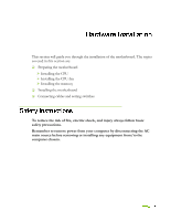
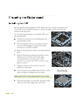
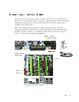
Most computer chassis have a base with mounting studs or spacers to allow the mother board to be secured to the chassis and help to prevent short circuits. If there are stud(s) that do not align with a mounting hole on the motherboard, it is recommended that you remove that stud(s) to prevent the possibility of a short circuit. In most cases, it is recommended to secure the motherboard using a minimum of eight (8) to ten (10) studs. Carefully place the motherboard onto the studs/spacers located inside the chassis. Align the mounting holes with the studs/spacers. Align the connectors to the I/O shield. Ensure that the fan assembly is aligned with the chassis vents according to the fan assembly instruction. Secure the motherboard with a minimum of eight-to-ten screws. This section takes you through all the connections necessary on the motherboard. This will include: Power Connections 24-pin ATX power (PWR1) 8-pin ATX 12V power (PWR2) Internal Headers Front panel IEEE 1394a USB Headers Audio COM FDD IDE
-
 1
1 -
2
-
3
-
4
-
5
-
6
-
7
-
8
-
9
-
10
-
11
-
12
-
13
-
 14
14 -
 15
15 -
 16
16 -
 17
17 -
 18
18 -
 19
19 -
 20
20 -
 21
21 -
 22
22 -
 23
23 -
 24
24 -
25
-
26
-
27
-
28
-
29
-
30
-
31
-
32
-
33
-
34
-
35
-
36
-
37
-
38
-
39
-
40
-
41
-
42
-
43
-
44
-
45
-
46
-
47
-
48
-
49
-
50
-
51
-
52
-
53
-
54
-
55
-
56
-
57
-
58
-
59
-
60
-
61
-
62
-
63
-
64
-
65
-
66
-
67
-
68
-
69
-
70
-
71
-
72
-
73
-
74
-
75
-
76
-
77
-
78
-
79
-
80
-
81
-
82
-
83
-
84
 |
 |