Fluke Ti55FT-20 User Manual
Fluke Ti55FT-20 Manual
 |
View all Fluke Ti55FT-20 manuals
Add to My Manuals
Save this manual to your list of manuals |
Fluke Ti55FT-20 manual content summary:
- Fluke Ti55FT-20 | User Manual - Page 1
® TiR2,TiR3,TiR4, Ti40,Ti45,Ti50,Ti55 IR FlexCam Thermal Imagers Users Manual January 2007, Rev.2, 5/09 ©2007, 2009 Fluke Corporation. All rights reserved. Specifications subject to change without notice. All product names are trademarks of their respective companies. - Fluke Ti55FT-20 | User Manual - Page 2
authority to extend a greater or different warranty on behalf of Fluke. Warranty support is available only if product is purchased through a Fluke authorized sales outlet or Buyer has paid the applicable international price. Fluke reserves the right to invoice Buyer for importation costs of repair - Fluke Ti55FT-20 | User Manual - Page 3
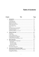
1-1 Introduction 1-1 Contacting Fluke 1-2 Safety Information 1-2 Standard Accessories 1-4 Charge and Insert Battery 1-6 Power Camera On 1-7 Insert Memory Card 1-8 Focus...1-8 Set Temperature Level and Span 1-9 Set IR-Fusion® Blend Level 1-9 Capturing an Image 1-10 SmartView Software for - Fluke Ti55FT-20 | User Manual - Page 4
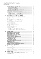
Manual Level and Span 4-3 Automatic Level and Span 4-4 Arbitrary Fixed Temperature Level and Span 4-4 Using Palette Saturation Colors 4-5 Using Display Screen Temperature Markers 4-7 Annotations 4-9 Adding Annotations to Saved Images Image Alignment 5-1 Focusing 5-2 Adjusting IR-VL IR-Fusion - Fluke Ti55FT-20 | User Manual - Page 5
Contents (continued) Viewing Camera and Battery Information 8-2 Charging the Batteries 8-3 Recalibrating the Batteries 8-4 Conserving Battery Power 8-5 Appendices A Glossary A-1 B Troubleshooting B-1 C Emissivity Values C-1 D Camera Specifications and Dimensions D-1 E Resources and - Fluke Ti55FT-20 | User Manual - Page 6
TiR2,TiR3,TiR4,Ti40,Ti45,Ti50,Ti55 Users Manual iv - Fluke Ti55FT-20 | User Manual - Page 7
Table Title Page 1-1. Symbols 1-4 1-2. Standard Accessories 1-6 2-1. Camera Parts--Descriptions 2-6 2-2. Display Screen--Descriptions 2-11 2-3. Programmable Functions 2-14 4-1. Standard Saturation Colors 4-8 8-1. Remaining Battery Charge Indicators 8-3 8-2. Battery Charging Status 8-4 v - Fluke Ti55FT-20 | User Manual - Page 8
TiR2,TiR3,TiR4,Ti40,Ti45,Ti50,Ti55 Users Manual vi - Fluke Ti55FT-20 | User Manual - Page 9
Battery 1-7 1-3. Turning the Power On and Off 1-7 1-4. Inserting a Memory Card 1-8 1-5. Focusing the Camera 1-8 1-6. Setting the Level and Span 1-9 1-7. Setting the IR-Fusion® Blend Level 1-10 1-8. Capturing an Image and Removing a Memory Card 2-13 5-1. Aligning the 20-mm Lens 5-2 vii - Fluke Ti55FT-20 | User Manual - Page 10
TiR2,TiR3,TiR4,Ti40,Ti45,Ti50,Ti55 Users Manual viii - Fluke Ti55FT-20 | User Manual - Page 11
enhanced detail. This is especially helpful in low contrast scenes where the temperature differential is minimal and the infrared image appears to be all one color. The IR FlexCam is available in 7models. The TiR2, Ti40 and Ti45 cameras use a detector with 160 x 120 resolution. The TIR3, TiR4 - Fluke Ti55FT-20 | User Manual - Page 12
designed to familiarize you with the most important aspects of your camera and guide you in using the features of this system. This manual provides instruction on how to capture high quality images; however, thermography is a sophisticated field often requiring special training that is not covered - Fluke Ti55FT-20 | User Manual - Page 13
and may harm or permanently damage your camera's IR detector. • Your camera was calibrated prior to 9000 programs require more frequent checks for certification. Contact Fluke for details. • Your camera requires three minutes to manual or the protection provided by the equipment may be impaired. - Fluke Ti55FT-20 | User Manual - Page 14
. Do not mix with the solid / waste stream. Spent batteries should be disposed of by a qualified recycler or hazardous materials handler per local regulations. Contact your authorized Fluke Service Center for recycling information. Standard Accessories If any of the standard accessories shown - Fluke Ti55FT-20 | User Manual - Page 15
1 Introduction Standard Accessories 3 4 8 11 5 7 6 10 9 15 13 12 14 16 Figure 1-1. Standard Accessories eii001.eps 1-5 - Fluke Ti55FT-20 | User Manual - Page 16
USB Adapter N Getting Started Guide O SmartView® Software CD (includes SmartView Users Manual) P FlexCam Documentation CD (Users Manuals) Charge and Insert Battery Charge the batteries for 3 hours before use. Use only the rechargeable batteries supplied. A battery is fully charged when the - Fluke Ti55FT-20 | User Manual - Page 17
30 seconds in order to maintain a crisp, clear, real-time image. Three minutes after powering on the camera, the temperature measurement accuracy will be within the specification requirements. Note Because of the thermal mass for the optional 54 mm lens, a warm up period of 30 minutes is necessary - Fluke Ti55FT-20 | User Manual - Page 18
camera display screen. 4. Close the cover. Figure 1-4. Inserting a Memory Card eii004.eps Focus Remove the lens cap, point the lens at the target, and manually rotate the lens with your finger, as shown in Figure 1-5, until the image is in focus. Figure 1-5. Focusing the Camera eii005.eps 1-8 - Fluke Ti55FT-20 | User Manual - Page 19
2. Press G again as needed to properly scale the image. Level & Span Figure 1-6. Setting the Level and Span eii006.eps Set IR-Fusion® Blend Level Note IR-Fusion® blending is disabled with optional 10 and 54-mm lenses. 1. Press and hold G until the IR-Fusion® blend level dialog box appears on the - Fluke Ti55FT-20 | User Manual - Page 20
TiR2,TiR3,TiR4,Ti40,Ti45,Ti50,Ti55 Users Manual Mouse Controller F1 F2 F3 Level & Span Figure 1-7. Setting the IR-Fusion® Blend Level eii007.eps Capturing an Image 1. Tap once (shown in Figure 1-8) to pause the live image. 2. Review the image and camera settings. 3. Press and hold for 2 seconds - Fluke Ti55FT-20 | User Manual - Page 21
your infrared and visible light control images • Create and print detailed, professional reports containing important image data SmartView image analysis software is compatible with any by double-clicking the setup.exe file. 3. Follow the on-screen instructions to complete the installation. 1-11 - Fluke Ti55FT-20 | User Manual - Page 22
TiR2,TiR3,TiR4,Ti40,Ti45,Ti50,Ti55 Users Manual 1-12 - Fluke Ti55FT-20 | User Manual - Page 23
for optimal viewing. You can also rotate the lens module to easily capture target images on ceilings, hidden above high objects, under low obstacles, or in other hard- improves your ability to identify and analyze thermal anomalies and to provide visible light control images for your reports. 2-1 - Fluke Ti55FT-20 | User Manual - Page 24
TiR2,TiR3,TiR4,Ti40,Ti45,Ti50,Ti55 Users Manual Camera Parts Camera features and controls are shown in Figures 2-1, 2-2, and 2-3 and described in Table 2-1. 1 2 3 4 5 F1 6 F2 7 F3 8 9 Fluke use only 10 11 Figure 2-1. Camera Back View 12 eii009.eps 2-2 - Fluke Ti55FT-20 | User Manual - Page 25
14 15 16 13 20 2 Camera Overview Camera Parts 21 19 17 18 Figure 2-2. Camera Front and Top View eii010.eps 22 23 Figure 2-3. Camera Bottom View eii011.eps 2-3 - Fluke Ti55FT-20 | User Manual - Page 26
reset camera. Can be accessed with a paper clip. See, "Appendix B - Troubleshooting". J Battery latch - Used to remove battery. K Liquid Crystal Display (LCD) screen - Sunlight-readable color display for viewing images and accessing camera menu functions. G LEVEL & SPAN button - Used to rescale - Fluke Ti55FT-20 | User Manual - Page 27
. T Hand strap - Adjustable strap for added stability when capturing images. U Neck strap mount - Pins for attaching neck and/or shoulder strap. V Tripod mount - Standard 1/4-20 threaded hole for mounting camera on tripod. W Battery - Fluke 7-volt lithium-ion battery for primary power. 2-5 - Fluke Ti55FT-20 | User Manual - Page 28
TiR2,TiR3,TiR4,Ti40,Ti45,Ti50,Ti55 Users Manual Camera Display Screen Display screen features and controls are shown in Figures 2-4, 2-5, and 2-6 and described in Table 2-2. Figure 2-4. Camera Display Screen - Example 1 eii012.eps 2-6 - Fluke Ti55FT-20 | User Manual - Page 29
2 Camera Overview Camera Display Screen Figure 2-5. Camera Display Screen - Example 2 eii013.eps Figure 2-6. Camera Display Screen - Example 3 eii014.eps 2-7 - Fluke Ti55FT-20 | User Manual - Page 30
,Ti40,Ti45,Ti50,Ti55 Users Manual Table 2-2. Display Screen - Descriptions Item Description A Color palette - Palette used in displayed image; click to change color palette M Power source - Icon indicating either AC power or battery level; click to identify remaining time available from current - Fluke Ti55FT-20 | User Manual - Page 31
temperature in the image; always in image; always in blue (when enabled). Q Analysis point - Temperature of marker point in the image image appears in the rest of the display screen (when enabled). IR-Fusion® blend level dialog box - Used to change the IR-Fusion® T blend level from full infrared (IR - Fluke Ti55FT-20 | User Manual - Page 32
Manual Programming Function Buttons You can assign any of the functions described in Table 2-3 to any one of three programmable buttons: A, B, C (see Appendix F for a list of default settings). See programming instructions marker points or areas to the image and displaying temperatures near them. - Fluke Ti55FT-20 | User Manual - Page 33
cycle through the image enhancement settings: "Off," "Normal," "Medium," and "High." Each time you press the function button, the next setting takes affect. Picture-in-Picture - Used to quickly switch between full screen view and picture-in-picture view. Recalibrate - Used to manually trigger an - Fluke Ti55FT-20 | User Manual - Page 34
in the section of this manual that corresponds to the selected task supported, languages) - Calibration Information (for example, lens type) - Revision (including OS build, DSP version, software version) • Camera Settings • Browse Images • Image Settings • Annotate Image • Start Sequence • Save Image - Fluke Ti55FT-20 | User Manual - Page 35
newer copyright date. Do not use other memory card brands. W Caution To avoid loss of images in the event of a technical problem with either the Camera or the memory card, be sure to regularly transfer the images you save on the CompactFlash memory card to a computer hard drive and/or other back-up - Fluke Ti55FT-20 | User Manual - Page 36
,TiR3,TiR4,Ti40,Ti45,Ti50,Ti55 Users Manual W Caution To avoid damaging the memory card card. W Caution To prevent data loss or corruption, do not remove the memory card while saving an image. 1. Lift memory card slot cover. 2. Firmly press the memory card ejection button. The card partially slides - Fluke Ti55FT-20 | User Manual - Page 37
quickly tap the trigger ( ) button. The word "Paused" appears in the upper left corner of the display, and the live target area image is paused enabling you to analyze the image and determine if it is acceptable enough to save. If not, quickly tap again to return to scan target mode. If - Fluke Ti55FT-20 | User Manual - Page 38
TiR2,TiR3,TiR4,Ti40,Ti45,Ti50,Ti55 Users Manual The image name is displayed in the upper left corner of the display screen. Tap to return to scan target mode. View Saved Image To view images saved on the memory card: 1. Make sure memory card is inserted (see Chapter 2), then tap F. 2. Use the mouse - Fluke Ti55FT-20 | User Manual - Page 39
the popup menu. 3. Tap E. 4. Position the pointer over the Files tab and tap E. 5. Position the pointer over Delete all images and tap E. 6. Select Yes (if you do not want to delete all images, select No or Cancel). 7. Tap to return to scan target mode. Electronic Zoom From normal view, you can zoom - Fluke Ti55FT-20 | User Manual - Page 40
TiR2,TiR3,TiR4,Ti40,Ti45,Ti50,Ti55 Users Manual Saved Image Information Opening the Info tab within the Image Settings menu window enables you to view a variety of information about a saved image, including: the name of the camera manufacturer, camera model number, lens focal length and f-number, - Fluke Ti55FT-20 | User Manual - Page 41
target temperatures. Use the table in Appendix C, which lists the emissivity values of some common materials, as a guide to setting correct emissivity values. To set the emissivity value for an image in the camera: 1. Use the mouse controller to position the pointer over the emissivity value on the - Fluke Ti55FT-20 | User Manual - Page 42
TiR2,TiR3,TiR4,Ti40,Ti45,Ti50,Ti55 Users Manual Fixed Image Function You can also set the emissivity and background temperature values by opening the Image Settings menu and clicking the Emissivity tab. From here, you can enable or disable the Fixed Image function. When this function is enabled, the - Fluke Ti55FT-20 | User Manual - Page 43
to help you visualize the relation between temperature and color. Setting the span to the narrowest range possible provides the highest quality images. When using the manual or automatic level and span function, if the center box function is enabled, the temperature updates are done based on the - Fluke Ti55FT-20 | User Manual - Page 44
,Ti40,Ti45,Ti50,Ti55 Users Manual Automatic Level and Span When you enable the automatic level and span function, the color palette temperatures are regularly updated to the current maximum and minimum temperatures in the image at a time interval you set (from 1/4 second to 10 seconds). To enable - Fluke Ti55FT-20 | User Manual - Page 45
down arrow and tap E. 5. Use the mouse controller to scroll to "Manual" and tap E. 6. Position the pointer over either: • The Palette Range palette level and span, the full color range is used to display the image. This same temperature color mapping is maintained until you set the level and - Fluke Ti55FT-20 | User Manual - Page 46
TiR2,TiR3,TiR4,Ti40,Ti45,Ti50,Ti55 Users Manual extremes are displayed at the ends of the color disable the saturation colors function: 1. Tap F. 2. Use the mouse controller to position the pointer over Image Settings on the popup menu and tap E. 3. Position the pointer over the Palette tab and tap - Fluke Ti55FT-20 | User Manual - Page 47
appear on the display screen in scan target mode and/or on a saved image you open. With the mouse pointer marker enabled, you can move the pointer display screen to reveal the spot temperatures at any place on the image. Note To add advanced markers, see Chapter 7, User-Defined Temperature Markers - Fluke Ti55FT-20 | User Manual - Page 48
TiR3,TiR4,Ti40,Ti45,Ti50,Ti55 Users Manual 4. Position pointer over one of the temperatures you want to appear in the image (Center Point, Center Box, Hot want to appear on the image. In scan target mode, you can also select Onscreen Logo. A check mark indicates the Fluke logo will appear on the - Fluke Ti55FT-20 | User Manual - Page 49
over the right or left arrow key to scroll to the page containing the image you want to annotate; position pointer over the image and double click E to open. 5. In the open image, tap F, then select Annotate Image from the popup menu. 6. Position the pointer over the annotation category you want to - Fluke Ti55FT-20 | User Manual - Page 50
TiR2,TiR3,TiR4,Ti40,Ti45,Ti50,Ti55 Users Manual annotation items for the selected category appear on categories. 9. Tap to accept setting change and return to the open image. An annotation icon appears in the upper part of the image. 10. Tap once more to return to scan target mode. To delete, - Fluke Ti55FT-20 | User Manual - Page 51
on the popup menu. 3. Position the pointer over the Files tab and tap E. 4. Position the pointer over the "Auto-Start Notation Wizard When Saving New Image" box and tap E. A check mark appears in the box indicating the feature is enabled. 5. Tap to accept setting change and return to scan target - Fluke Ti55FT-20 | User Manual - Page 52
TiR2,TiR3,TiR4,Ti40,Ti45,Ti50,Ti55 Users Manual Creating Annotations Lists in SmartView In addition to managing your annotations using the software onto your computer (see Chapter 1), refer to the software's online Help menu for instructions on how to create and/or edit annotations lists. 4-12 - Fluke Ti55FT-20 | User Manual - Page 53
for viewing and analysis. The visible light image and the infrared image are lined up for distances greater than 50 cm (approximately 2 ft). Image alignment is disabled when using the optional 10 and 54-mm lenses. To ensure proper image alignment with the standard 20-mm lens, the lens must be - Fluke Ti55FT-20 | User Manual - Page 54
,Ti40,Ti45,Ti50,Ti55 Users Manual Alignment Mark Figure 5-1. Aligning the 20-mm Lens eii021.eps Focusing Prior to capturing images using the visible light module and IR-Fusion®, it is important to make sure the target object is in focus. As you rotate the infrared (IR) lens to focus the camera - Fluke Ti55FT-20 | User Manual - Page 55
This feature is disabled with optional 10 and 54-mm lenses. You can change the IR-Fusion® blend level from full infrared (IR) to full visible light (VL) or some combination in between. When the IR-Fusion® blend level is set to full IR, 100% of the image is IR. When the IR-Fusion® blend level is set - Fluke Ti55FT-20 | User Manual - Page 56
,Ti45,Ti50,Ti55 Users Manual Using Full Screen or Picture-in-Picture View In the full screen view, the infrared (IR) target object image takes up the entire display screen using the IR-Fusion® blend setting you have selected. For example, if the IR-Fusion® blend setting is Full IR, then the infrared - Fluke Ti55FT-20 | User Manual - Page 57
If both functions are enabled, the torch operates continuously, while the flash comes on during the image capture. The torch enabled function times out after 60 seconds. Limit torch use to save battery power. Assign the Torch function to a programmable button (see Chapter 2). Then, to cycle between - Fluke Ti55FT-20 | User Manual - Page 58
this function enabled, both the visible light and the infrared images are captured. You can view the images using the Full IR or Full Visible settings or blended in between. With the record control image function disabled, only the infrared image is saved. Note The setting to either record or not - Fluke Ti55FT-20 | User Manual - Page 59
*To avoid injury, use your camera's Class 2 laser pointer only as instructed. Use the laser function to help you point out the object you are problem is physically located. Using appropriate IR-Fusion® blend levels and color palette settings allows the red laser dot to be in the visible light image - Fluke Ti55FT-20 | User Manual - Page 60
Ti40,Ti45,Ti50,Ti55 Users Manual Using Color Alarms Note This feature is not available on the TiR3 or Ti50. The color alarm function allows you to highlight target object areas of thermal interest by selectively fusing the visible light image with portions of the infrared image. For example, you can - Fluke Ti55FT-20 | User Manual - Page 61
indicates the function is enabled. If you selected "Temperatures are Inside Specified Range," you cannot change the Max or Min check boxes. 9. Continue to Step 10 to set the alarm temperature range, or go to Step 12 if finished. To set color alarm temperature range (maximum and minimum temperatures - Fluke Ti55FT-20 | User Manual - Page 62
TiR2,TiR3,TiR4,Ti40,Ti45,Ti50,Ti55 Users Manual To adjust the color alarm temperature limits from the color palette: 1. Position the pointer over the color alarm temperature limit the value. 3. When you reach the desired temperature, tap to accept setting change and return to scan target mode. 5-10 - Fluke Ti55FT-20 | User Manual - Page 63
screen brightness for better viewing options in various lighting conditions. Note For maximum battery life, use the dimmest setting possible that still enables you to clearly see the display screen images. To adjust the display screen brightness and high brightness timeout time: 1. Tap F. 2. Use - Fluke Ti55FT-20 | User Manual - Page 64
TiR4,Ti40,Ti45,Ti50,Ti55 Users Manual Hiding Display Screen Task Bar For more image viewing area, you can hide the -Hide Task Bar function: 1. Tap F. 2. Use the mouse controller to position the pointer over Image Settings on the popup menu. 3. Tap E. 4. Position the pointer over the Display tab and - Fluke Ti55FT-20 | User Manual - Page 65
You can change the temperature calibration range as needed: the narrower the range the better the image quality, which enables you to see smaller temperature variances. The wider the range the lower the image quality; however, you are able to see a greater range of temperature variances. To set the - Fluke Ti55FT-20 | User Manual - Page 66
TiR2,TiR3,TiR4,Ti40,Ti45,Ti50,Ti55 Users Manual Note Lens selection cannot be changed on a paused or saved image. Be sure to select the correct lens prior to pausing or saving an image. 1. Tap F. 2. Use the mouse controller to position the pointer over Camera Settings on the popup menu and tap E. 3. - Fluke Ti55FT-20 | User Manual - Page 67
6 Camera Setup Setting Date and Time 4. Tap to accept setting change and return to scan target mode. To change the time: 1. Use the mouse controller to position the pointer over the time field on the task bar. 2. Tap E. 3. Position pointer over the Time field you are changing (hour, minute, or - Fluke Ti55FT-20 | User Manual - Page 68
TiR2,TiR3,TiR4,Ti40,Ti45,Ti50,Ti55 Users Manual Changing the Language To change the language setting: 1. Tap F. 2. Use the mouse controller to position the pointer over Camera Settings on the popup menu. 3. Tap E - Fluke Ti55FT-20 | User Manual - Page 69
6 Camera Setup Naming Image Files 6. Tap to accept setting change and return to scan Naming Image Files When you save an image, its name is added to the upper left corner of the image display. An image name looks like this: IR00020060515_0001 • IR is prefix (The prefix assigned to the image is - Fluke Ti55FT-20 | User Manual - Page 70
,TiR3,TiR4,Ti40,Ti45,Ti50,Ti55 Users Manual Changing Image File Name Prefix To change the prefix used in the saved image name: Note This change affects only new images saved to the memory card and does change the prefix of previously saved images. 1. Tap F. 2. Use the mouse controller to position - Fluke Ti55FT-20 | User Manual - Page 71
on a TV, video projector, or video monitor. You can also record images on a video recorder. Video output can be set to NTSC, PAL, or disabled. Note Disable the video output function when not in use to save battery power. To select NTSC or PAL signal and enable/disable video output: 1. Plug the - Fluke Ti55FT-20 | User Manual - Page 72
TiR2,TiR3,TiR4,Ti40,Ti45,Ti50,Ti55 Users Manual 3. Use the mouse controller to position the pointer over Camera Settings on the popup menu. 4. function is enabled. When not in use, disable this function to conserve battery power. 9. Tap to accept setting change and return to scan target mode - Fluke Ti55FT-20 | User Manual - Page 73
enhancement, be sure to enable the function prior to scanning target areas and saving images. To adjust the image enhancement level: 1. Tap F. 2. Use the mouse controller to position the pointer over Image Settings on the popup menu and tap E. 3. Position the pointer over "None," "Normal," "Medium - Fluke Ti55FT-20 | User Manual - Page 74
sequence. 5. Position the pointer over the right or left arrows next to Interval (sec) to set the number of seconds between images. 6. Position pointer over the Manual radio button and select. 7. Tap to accept setting change and return to scan target mode. To trigger the Auto Capture function using - Fluke Ti55FT-20 | User Manual - Page 75
for areas, select from Min. Avg., Max.). 8. Select the Over or Under radio button. 9. Use the right/left arrows to set the temperature trigger point. 10. Select the "Save all images after trigger" box if you want to save all images after the initial trigger, or, leave the box unchecked to save only - Fluke Ti55FT-20 | User Manual - Page 76
,TiR3,TiR4,Ti40,Ti45,Ti50,Ti55 Users Manual Using User-Defined Display Screen Temperature Markers add spot temperature markers to the display screen from either scan target mode or from an open image: 1. Use the mouse controller to position the pointer over the crosshair icon in the Marker toolbar - Fluke Ti55FT-20 | User Manual - Page 77
toolbar. 2. Tap E. 3. Use the mouse controller to move the pointer to the image area desired. 4. Tap E to place the starting point, then use the mouse toolbar and return either to scan target mode or to the open image. From an open image, tap again to return to scan target mode. To change the - Fluke Ti55FT-20 | User Manual - Page 78
TiR2,TiR3,TiR4,Ti40,Ti45,Ti50,Ti55 Users Manual 6. Tap the programmable button to close the Marker toolbar and return either to scan target mode or to the open image. From an open image, tap again to return to scan target mode. To remove, rename, or annotate spot temperature and/or area markers from - Fluke Ti55FT-20 | User Manual - Page 79
from the camera and see the word "Calibrating" appear on the display screen. The image is frozen for approximately 1-2 seconds during the calibration process. You may also want to manually trigger an internal calibration to adjust for changing environmental conditions, for example, you move from - Fluke Ti55FT-20 | User Manual - Page 80
TiR2,TiR3,TiR4,Ti40,Ti45,Ti50,Ti55 Users Manual 7-8 - Fluke Ti55FT-20 | User Manual - Page 81
Chapter 8 Camera Care Cleaning the IR Lens, VLCM, Display Screen, and Body For optimal performance camera, use compressed air to remove large particles and dust prior to using a cloth. To clean the IR lens and the VLCM lenses and windows: • Lightly rub the lens with a soft cotton cloth slightly - Fluke Ti55FT-20 | User Manual - Page 82
a wide angle f 0.8 10.5-mm focal length lens to capture larger targets at short distances and a narrow angle f 1.0 54-mm focal length lens to fluke.com. Viewing Camera and Battery Information The Info tab within the Camera Info window contains a list of key features such as IR refresh rate, IR image - Fluke Ti55FT-20 | User Manual - Page 83
V AC input voltage and 50 or 60 Hz input frequency. The charger has a recalibration feature to maintain correct capacity monitoring. When using battery power, a battery symbol appears in the far right side of the camera display screen task bar. The remaining charge capacity is indicated as shown in - Fluke Ti55FT-20 | User Manual - Page 84
TiR2,TiR3,TiR4,Ti40,Ti45,Ti50,Ti55 Users Manual To charge camera batteries: Note Charge at least one battery for 3 hours before use. Two batteries charge sequentially. The second battery remains in standby mode until the first battery is charged. 1. Connect battery charger AC power supply to a power - Fluke Ti55FT-20 | User Manual - Page 85
battery in the right charging bay while recalibrating a battery in the left bay. To recalibrate a battery: 1. Insert the battery into the left bay of the battery been in standby for 10 minutes (you can change this time). You can manually switch to standby mode as well. To manually switch from full - Fluke Ti55FT-20 | User Manual - Page 86
TiR2,TiR3,TiR4,Ti40,Ti45,Ti50,Ti55 Users Manual To change the standby to off timeout time: 1. Tap F. 2. Use the mouse controller to position the pointer over Camera Settings on the popup menu. 3. Tap E. 4. - Fluke Ti55FT-20 | User Manual - Page 87
Appendices Appendix Title Page A Glossary A-1 B Troubleshooting B-1 C Emissivity Values C-1 D Camera Specifications and Dimensions D-1 E Resources and References E-1 F Camera Default Settings F-1 - Fluke Ti55FT-20 | User Manual - Page 88
TiR2,TiR3,TiR4,Ti40,Ti45,Ti50,Ti55 Users Manual - Fluke Ti55FT-20 | User Manual - Page 89
from the fact that a cold blackbody appears visually black. Color Palette Color representation of the temperatures (temperature scale) in a displayed image. Electro Static Discharge (ESD) event A single-event, rapid transfer of electrostatic charge between two objects, usually resulting when two - Fluke Ti55FT-20 | User Manual - Page 90
from 0.7µm to microwave. Infrared Camera Electronics, lens, and detector combinations that give the user an image, that can be viewed or recorded, of energy in the infrared spectrum. Infrared, Thermal The portion of the infrared spectrum from which the majority of heat energy is recorded. This - Fluke Ti55FT-20 | User Manual - Page 91
across which the color palette (temperature scale) is mapped. Target An object being thermally photographed. Temperature Scale - The temperatures represented by the color palette (palette temperatures this measurement to an equivalent surface temperature. Thermogram - An infrared image. A-3 - Fluke Ti55FT-20 | User Manual - Page 92
TiR2,TiR3,TiR4,Ti40,Ti45,Ti50,Ti55 Users Manual A-4 - Fluke Ti55FT-20 | User Manual - Page 93
is not Insert a charged battery. inserted. The battery is not Charge the battery. See Chapter 8. charged. An improper Compact Flash memory card is inserted. Use SanDisk-brand Compact Flash memory card with a 2003 or newer copyright date. W Caution To avoid problems saving images, do not use other - Fluke Ti55FT-20 | User Manual - Page 94
,TiR3,TiR4,Ti40,Ti45,Ti50,Ti55 Users Manual Table B-1. Troubleshooting Tips (cont.) Symptom Possible Reason Possible the memory card. Reformatting the memory card will erase all images stored on the card. Camera will not save an image. An electrostatic discharge (ESD) event has taken place. - Fluke Ti55FT-20 | User Manual - Page 95
Calibration Range, in Chapter 6. Visible light and IR images are not properly aligned. Incorrect focus, optional lenses, or 20-mm lens not properly aligned. Image alignment is disabled with 10 and 54-mm lenses. Adjust the alignment after the images are downloaded to the SmartView software. Align - Fluke Ti55FT-20 | User Manual - Page 96
TiR2,TiR3,TiR4,Ti40,Ti45,Ti50,Ti55 Users Manual Before You Contact Us To better assist you and to minimize your call time, please have the following information ready to share with a customer service representative before contacting Fluke Corporation: • OCA Version, DSP Version, and MSP Version You - Fluke Ti55FT-20 | User Manual - Page 97
Appendix C Emissivity Values Use the emissivity values shown in Table C-1 as a guide to properly setting the emissivity value on your Camera. Table C-1. Emmisivity Values Brick, glazed, rough 0 0.85 Brick, refractory, rough 0 0.94 Bronze, porous, rough 0 0.55 Bronze, polished 0 0.10 C-1 - Fluke Ti55FT-20 | User Manual - Page 98
Users Manual Table C-1. Emissivity Values of Common Materials (cont.) Material Temperature (°C) Emissivity Carbon, purified 0 0.80 Cast iron, rough casting 0 0.81 Cast iron, polished 0 0.21 Charcoal, powdered 0 0.96 Chromium, polished 0 0.10 Clay, fired 0 0.91 Concrete 0 0.54 - Fluke Ti55FT-20 | User Manual - Page 99
, white 0 0.87 Lampblack 0 0.96 Lead, gray 0 0.28 Lead, oxidized 0 0.63 Lead, red, powdered 0 0.93 Lead, shiny 0 0.08 Mercury, pure 0 0.10 Nickel, on cast iron 0 0.05 Nickel, pure polished 0 0.05 Paint, silver finish 25 0.31 Paint, oil, average 0 0.94 Paper, black - Fluke Ti55FT-20 | User Manual - Page 100
TiR2,TiR3,TiR4,Ti40,Ti45,Ti50,Ti55 Users Manual Table C-1. Emissivity Values of Common Materials (cont.) Material Temperature (°C) Emissivity Quartz 0 0.93 Rubber 0 0.93 0 0.56 Tar paper 0 0.92 Tin, burnished 0 0.05 Tungsten 0 0.05 Water 0 0.98 Zinc, sheet 0 0.20 C-4 - Fluke Ti55FT-20 | User Manual - Page 101
D-1. TiR2, Ti45 and Ti40 Specifications Model Name Ti45 and TiR2 Imaging Performance Ti40 Detector 160 x 120 Focal Plane Array (FPA), screen to determine the refresh rate for your specific camera. Spectral Band Thermal Sensitivity 8 µm to 14 µm ≤0.080 °C at 30 °C (80 mK) ≤0. - Fluke Ti55FT-20 | User Manual - Page 102
Level, Span, Auto Adjust (continuous/manual) Image Browsing Full-screen and thumbnail Enhanced Text Annotation User definable, n/a automatically included in reports Programmable Image Capture 20mm f/0.8 Germanium Automatically capture n/a thermal images (program) Standard Optics Field of - Fluke Ti55FT-20 | User Manual - Page 103
Range 2, 3, and 4 are not available on the TiR2 Range 1 = -20 °C to 100 °C (-4˚F to 212˚F) Range 2 = -20 °C to 350 °C (-4 °F to 662 °F) Range 2 = -20 °C to 350 °C (-4 °F to 662 °F) Range 3 = 250 °C to (0.01 increments) Power Battery Type Li-Ion Smart Battery, rechargeable, field-replaceable D-3 - Fluke Ti55FT-20 | User Manual - Page 104
RS170 EIA/NTSC or CCIR/PAL composite video Physical Characteristics 4.4 lbs including battery Size 71 mm x 262 mm x 196 mm (2.8 in x 10.5 in x 7.7 in) Tripod Mounting ¼ in - 20 UNC Environmental Operating Temp. -10 °C to +50 °C (14 °F to 122 °F) Storage Temp. -40 °C to +70 °C (-40 °F to - Fluke Ti55FT-20 | User Manual - Page 105
years and begins on date of shipment. Standard Equipment IR Camera with 20-mm f/0.8 lens Compact Flash Card USB Card Reader SmartView™ Software Shoulder Strap 2 Rechargeable Batteries Premium Carrying Case Battery Charger User Manual Video Cable AC Adapter Optional Equipment Power Cable for - Fluke Ti55FT-20 | User Manual - Page 106
lux Focus Distance 50 cm to infinity Exposure Auto Integrated Flash Manual or default for high quality visible light images Torch Light Mode For enhanced video imaging in dark areas IR-Fusion® Modes • Full screen IR image blended with visible image • Picture-in-picture blended with visible - Fluke Ti55FT-20 | User Manual - Page 107
specific camera. Spectral Band 8 µm to 14 µm Thermal Sensitivity ≤ 0.050 °C at 30 °C (50 mK) ≤ 0.070 °C at 30 °C (70 mK) Focusing Single Finger Manual Focus Electronic Zoom 2x, 4x, 8x 2x (2x, 4x when IR-Fusion® enabled) Digital Image Automatic Full-time Enhanced Enhancement Display and - Fluke Ti55FT-20 | User Manual - Page 108
Span, Auto Adjust (continuous/manual) Image Browsing Full-screen and thumbnail Enhanced Text User definable, n/a Annotation automatically included in reports Programmable Program camera to n/a Image Capture automatically capture thermal images Standard Optics 20mm f/0.8 Germanium Field - Fluke Ti55FT-20 | User Manual - Page 109
3 are not available on the TiR4 Range 2 is not available on the TiR3 Range 2 = -20 °C to 350 °C Range 2 = -20 °C to 350 °C (-4˚F to 662˚F) (-4 °F to 662 °F) Range 3 = 250 °C to (area min/max, average) Emissivity Correction Battery Type Based on user input. Variable from 0.01 to 1.0 (0.01 - Fluke Ti55FT-20 | User Manual - Page 110
,Ti55 Users Manual Table D-2. TiR3, TiR4, Ti55 and Ti50 Specifications (cont.) Model Name Ti55 and TiR4 Ti50 and TiR3 Battery Charging 2-bay 4.4 lbs including battery Size 71mm x 262mm x 196mm (2.8 in x 10.5 in x 7.7 in) Tripod Mounting 1/4 in - 20 UNC Environmental Operating -10 °C to - Fluke Ti55FT-20 | User Manual - Page 111
years and begins on date of shipment. Standard Equipment IR Camera with 20-mm f/0.8 lens Compact Flash Card USB Card Reader SmartView™ Software Shoulder Strap 2 Rechargeable Batteries Premium Carrying Case Battery Charger User Manual Video Cable AC Adapter Optional Equipment Power Cable for - Fluke Ti55FT-20 | User Manual - Page 112
Shield 54-mm Tele-photo Lens (9 °H x 6 °V) 10.5-mm Lens (42 °H x 32 °V) AC Adapter Visible Light Camera 1.3 M Active Pixels 1280 H x 1024 V Field of View 56° H x 46° V Sensitivity 1 lux Focus Distance Exposure 50 cm to infinity Auto Integrated Flash Torch Light Mode IR-Fusion® Modes Manual or - Fluke Ti55FT-20 | User Manual - Page 113
D Appendices Camera Specifications and Dimensions Camera dimensions are shown in Figures D-1 and D-2. 10.66 cm (4.2 in) 7.11 cm (2.8 in) Figure D-1. Camera Dimensions 26.67 cm (10.5 in) eii019.eps 19.55 cm (7.7 in) Figure D-2. Camera Dimensions - Height and Width eii020.eps D-13 - Fluke Ti55FT-20 | User Manual - Page 114
TiR2,TiR3,TiR4,Ti40,Ti45,Ti50,Ti55 Users Manual D-14 - Fluke Ti55FT-20 | User Manual - Page 115
Level I class, participants will: • Learn to think thermally • Learn about basic heat transfer theory • Discover how using an infrared sensor • Successfully capture images as well as document findings and write consistently provide high-quality data. Let Fluke Corporation assist you in developing a - Fluke Ti55FT-20 | User Manual - Page 116
TiR2,TiR3,TiR4,Ti40,Ti45,Ti50,Ti55 Users Manual E-2 - Fluke Ti55FT-20 | User Manual - Page 117
Settings, TiR2, Ti45 and Ti40 Models Setting Ti45 and TiR2 Camera Info Ti40 Info Battery Calendar Reference Only Reference Only Camera Settings Date Current Time Lens Calibration Range Current 20-mm/F.8 (initial from factory, subsequent settings are last user-setting even on "reset to - Fluke Ti55FT-20 | User Manual - Page 118
,TiR4,Ti40,Ti45,Ti50,Ti55 Users Manual Table F-1. Default Settings, TiR2, Ti45 and Ti40 Models (cont.) Setting Ti45 and TiR2 Ti40 High Brightness Timeout 30 seconds Standby Time Out 5 min Standby to Off Time 10 min Video Off Output Files File Prefix IR File 0 Sequence Auto-Start - Fluke Ti55FT-20 | User Manual - Page 119
Date Time Mouse MM-dd-yy HH:mm:ss Mouse Fast Sensitivity Fast Value Disabled Changes Save Reference Only Browse Images Reference Only VLCM Enable VLCM Enabled IR-Fusion® 100% IR Level Full PIP Screen/PIP Flash Enabled Disabled High Enabled Brightness Vivid Color Enabled F-3 - Fluke Ti55FT-20 | User Manual - Page 120
TiR2,TiR3,TiR4,Ti40,Ti45,Ti50,Ti55 Users Manual Table F-1. Default Settings, TiR2, Ti45 and Ti40 Models (cont.) Setting Ti45 and TiR2 Image Settings Ti40 Display Center Point Disabled Center Box Disabled Hot Disabled n/a Cursor Cold Disabled n/a Cursor Temp. Scale Enabled Auto- - Fluke Ti55FT-20 | User Manual - Page 121
Setting Ti45 and TiR2 Ti40 Background Temp 68 °F ...Fixed Image Disabled Color Palette Image Settings Color Palette Blue-Red Saturation Colors Automatic Adjustment PIC Standard Disabled Max. 1 n/a Images Interval 1sec n/a Trigger Manual n/a Markers Reference Only n/a F-5 - Fluke Ti55FT-20 | User Manual - Page 122
Manual Table F-1. Default Settings, TiR2, Ti45 and Ti40 Models (cont.) Setting Ti45 and TiR2 Ti40 Color Alarms Enable Onscreen Alarm Disabled Disabled Temps. Are TRUE n/a Inside Specified Range Max Calibration range maximum n/a Min Calibration range maximum n/a Annotate Images - Fluke Ti55FT-20 | User Manual - Page 123
Models Setting Ti55 and TiR4 Camera Info Ti50 and TiR3 Info Battery Calendar Reference Only Reference Only Camera Settings Date Current Time Current last user-setting even on "reset to factory defaults") Calibration Range -20 °C to 100 °C (-4 °F to 212 °F) Initial from factory, - Fluke Ti55FT-20 | User Manual - Page 124
TiR2,TiR3,TiR4,Ti40,Ti45,Ti50,Ti55 Users Manual Table F-2. Default Settings, TiR3, TiR4, Ti55 and Ti50 Models (cont.) Setting Ti55 and TiR4 Ti50 and TiR3 Video Output Off Files File Prefix IR File 0 Sequence Auto-Start Disabled n/a Notation Wizard Locale Temp. Units F Language - Fluke Ti55FT-20 | User Manual - Page 125
-Fusion® Level Ti55 and TiR4 Enabled 100% IR Ti50 and TiR3 Full PIP Screen/PIP Flash Enabled Disabled High Enabled Brightness Vivid Color Enabled Display Center Point Disabled Center Box Disabled Hot Cursor Disabled Image Settings n/a Cold Cursor Disabled n/a Temp. Scale Enabled - Fluke Ti55FT-20 | User Manual - Page 126
TiR2,TiR3,TiR4,Ti40,Ti45,Ti50,Ti55 Users Manual Table F-2. Default Settings, TiR3, TiR4, Ti55 and Ti50 Models (cont.) Setting Ti55 and TiR4 Ti50 and TiR3 Image Settings Mouse Temp Zoom Image Enabled 1x Image Off Enhance- ment Emissivity Emissivity 0.95 Background 68 °F Temp Fixed - Fluke Ti55FT-20 | User Manual - Page 127
Settings, TiR3, TiR4, Ti55 and Ti50 Models (cont.) Setting Ti55 and TiR4 Ti50 and TiR3 PIC Max. 1 n/a Images Interval 1sec n/a Trigger Manual n/a Markers Reference Only n/a Color Alarms Enable Onscreen Alarm Disabled Temps. Are Inside Specified Range TRUE Max Calibration - Fluke Ti55FT-20 | User Manual - Page 128
TiR2,TiR3,TiR4,Ti40,Ti45,Ti50,Ti55 Users Manual F-12 - Fluke Ti55FT-20 | User Manual - Page 129
image, 1-10, See save image mode and saving images center box temperatures, 2-9 centerpoint temperature, 2-8 centerpoint/centerbox, 2-10 charging batteries , 4-2 hiding, 6-2 compactflash memory card inserting, 1-8, 2-14 removing, 2-14 conserving battery power, 8-5 customer service, B-3 Index-1 - Fluke Ti55FT-20 | User Manual - Page 130
7-4 DSP version, B-4, See camera and battery information -E- electronic zoom, 2-10, 3-3 emissivity, 2-8 fixed image function, 4-2 setting value, 4-1 -F- factory auto, 4-4 setting temperature, manual, 4-3 level and span button. See camera overview -M- marker toolbar, 2-10, See display screen, user- - Fluke Ti55FT-20 | User Manual - Page 131
10 programmable image capture (PIC), 7-1 manual trigger, 7-2 start sequence, 2-11 stop sequence, 2-11 temperature trigger, 7-2 -R- record sequence of several images. See programmable image capture recording control images , 2-10, 5-5 training thermography, E-1 trigger button, 2-5 troubleshooting, B-1 - Fluke Ti55FT-20 | User Manual - Page 132
TiR2,TiR3,TiR4,Ti40,Ti45,Ti50,Ti55 Users Manual -Z- zoom. See electronic zoom Index-4
-
 1
1 -
 2
2 -
 3
3 -
 4
4 -
 5
5 -
 6
6 -
 7
7 -
8
-
9
-
10
-
11
-
12
-
13
-
14
-
15
-
16
-
17
-
18
-
19
-
20
-
21
-
22
-
23
-
24
-
25
-
26
-
27
-
28
-
29
-
30
-
31
-
32
-
33
-
34
-
35
-
36
-
37
-
38
-
39
-
40
-
41
-
42
-
43
-
44
-
45
-
46
-
47
-
48
-
49
-
50
-
51
-
52
-
53
-
54
-
55
-
56
-
57
-
58
-
59
-
60
-
61
-
62
-
63
-
64
-
65
-
66
-
67
-
68
-
69
-
70
-
71
-
72
-
73
-
74
-
75
-
76
-
77
-
78
-
79
-
80
-
81
-
82
-
83
-
84
-
85
-
86
-
87
-
88
-
89
-
90
-
91
-
92
-
93
-
94
-
95
-
96
-
97
-
98
-
99
-
100
-
101
-
102
-
103
-
104
-
105
-
106
-
107
-
108
-
109
-
110
-
111
-
112
-
113
-
114
-
115
-
116
-
117
-
118
-
119
-
120
-
121
-
122
-
123
-
124
-
125
-
126
-
127
-
128
-
129
-
130
-
131
-
132
 |
 |

®
TiR2,TiR3,TiR4,
Ti40,Ti45,Ti50,Ti55
IR FlexCam Thermal Imagers
Users Manual
January 2007, Rev.2, 5/09
©
2007, 2009 Fluke Corporation. All rights reserved.
Specifications subject to change without notice.
All product names are trademarks of their respective companies.