Fluke Ti55FT-20 User Manual - Page 53
Visible Light Camera Module VLCM, Enabling/Disabling Visible Light Camera, Module
 |
View all Fluke Ti55FT-20 manuals
Add to My Manuals
Save this manual to your list of manuals |
Page 53 highlights
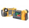
Chapter 5 Visible Light Camera Module (VLCM) Enabling/Disabling Visible Light Camera Module To enable/disable the visible light camera module: 1. Tap F. 2. Use the mouse controller to position the pointer over Camera Settings on the popup menu and tap E. 3. Position the pointer over the VLCM tab and tap E. You may need to position the pointer over the right or left arrow and tap E to scroll to the VLCM tab. 4. Position the pointer over the Enable Visible Light Camera box; tap E to add or remove a check mark. A check mark indicates the function is enabled. 5. Tap to accept setting change and return to scan target mode. Using Image Alignment Image alignment is an automatic adjustment that occurs as you focus the infrared camera lens. This feature is only available with the 20-mm lens. The visible light image and the infrared image are lined up based on the focusing distance of the infrared lens so that they may be combined for viewing and analysis. The visible light image and the infrared image are lined up for distances greater than 50 cm (approximately 2 ft). Image alignment is disabled when using the optional 10 and 54-mm lenses. To ensure proper image alignment with the standard 20-mm lens, the lens must be aligned correctly when you install it on the camera. Correct alignment is achieved by installing the lens such that the white alignment marking on the lens lines up with the corresponding mark on the camera housing as shown in Figure 5-1. 5-1
-
 1
1 -
2
-
3
-
4
-
5
-
6
-
7
-
8
-
9
-
10
-
11
-
12
-
13
-
14
-
15
-
16
-
17
-
18
-
19
-
20
-
21
-
22
-
23
-
24
-
25
-
26
-
27
-
28
-
29
-
30
-
31
-
32
-
33
-
34
-
35
-
36
-
37
-
38
-
39
-
40
-
41
-
42
-
43
-
44
-
45
-
46
-
47
-
 48
48 -
 49
49 -
 50
50 -
 51
51 -
 52
52 -
 53
53 -
 54
54 -
 55
55 -
 56
56 -
 57
57 -
 58
58 -
59
-
60
-
61
-
62
-
63
-
64
-
65
-
66
-
67
-
68
-
69
-
70
-
71
-
72
-
73
-
74
-
75
-
76
-
77
-
78
-
79
-
80
-
81
-
82
-
83
-
84
-
85
-
86
-
87
-
88
-
89
-
90
-
91
-
92
-
93
-
94
-
95
-
96
-
97
-
98
-
99
-
100
-
101
-
102
-
103
-
104
-
105
-
106
-
107
-
108
-
109
-
110
-
111
-
112
-
113
-
114
-
115
-
116
-
117
-
118
-
119
-
120
-
121
-
122
-
123
-
124
-
125
-
126
-
127
-
128
-
129
-
130
-
131
-
132
 |
 |
