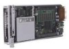
Contents
List of Figures
1-1
Enclosure components
........................................................................................................................
1-2
1-2
Server blade components
....................................................................................................................
1-3
1-3
Server blade components
....................................................................................................................
1-4
2-1
Removing a hot-plug power supply
....................................................................................................
2-5
2-2
Extending the fan cage
........................................................................................................................
2-6
2-3
Removing a hot-plug fan
....................................................................................................................
2-7
2-4
Pressing the power button on a server blade
.......................................................................................
2-8
2-5
Pressing the enclosure power button on the rear panel (cables removed for clarity)
........................
2-10
2-6
Disconnecting the power cords from the rear panel
.........................................................................
2-11
2-7
Removing the server blade from the enclosure
.................................................................................
2-12
2-8
Removing a one-bay server blade blank
...........................................................................................
2-13
2-9
Removing a five-bay server blade blank
...........................................................................................
2-13
2-10
Removing the interconnect tray from the enclosure
.........................................................................
2-14
2-11
Removing the enclosure from the rack
.............................................................................................
2-16
2-12
Opening the access door
...................................................................................................................
2-17
2-13
Disconnecting the fan cable from the power backplane
...................................................................
2-19
2-14
Removing the fan cage from the enclosure
.......................................................................................
2-20
2-15
Removing the fan backplane assembly
.............................................................................................
2-21
2-16
Removing the Integrated Administrator module from the interconnect tray
....................................
2-22
2-17
Disconnecting the enclosure status cable from the server blade backplane
......................................
2-23
2-18
Removing the enclosure status assembly from the enclosure
...........................................................
2-24
2-19
Removing a DIMM
...........................................................................................................................
2-25
2-20
DIMM socket keys for the ProLiant BL10e server blade
.................................................................
2-25
2-21
DIMM socket keys for the ProLiant BL10e G2 server blade
...........................................................
2-26
2-22
Replacing a DIMM
...........................................................................................................................
2-26
2-23
Removing the hard drive assembly from a server blade
...................................................................
2-27
2-24
Locating and removing the battery
...................................................................................................
2-28
2-25
Removing the center wall assembly from the enclosure
...................................................................
2-29
2-26
Installing the Integrated Administrator module onto the interconnect tray
......................................
2-30
3-1
Installing a diagnostic adapter
............................................................................................................
3-5
4-1
ProLiant C-GbE Interconnect Switch connectors
...............................................................................
4-2
4-2
RJ-21 patch panel connectors
.............................................................................................................
4-3
4-3
RJ-45 patch panel connectors
.............................................................................................................
4-4
4-4
Fan cable connector on the center wall assembly
...............................................................................
4-5
4-5
Enclosure status cable connector on the server blade backplane
........................................................
4-5
4-6
Identifying the server blade connectors
..............................................................................................
4-6
4-7
Diagnostic adapter connectors
............................................................................................................
4-7
4-8
Server blade and enclosure front panel buttons
..................................................................................
4-8
4-9
Enclosure rear panel buttons
...............................................................................................................
4-9
4-10
Maintenance switch
..........................................................................................................................
4-10
4-11
Enclosure front panel LEDs
..............................................................................................................
4-11
4-12
Rear panel LEDs with the interconnect switch interconnect tray
.....................................................
4-12
4-13
Rear panel LEDs with the RJ-21 patch panel interconnect tray
.......................................................
4-14
4-14
Rear panel LEDs with RJ-45 patch panel interconnect tray
.............................................................
4-16
4-15
Hot-plug fan health LEDs
.................................................................................................................
4-17
4-16
Server blade LEDs
............................................................................................................................
4-18
4-17
Diagnostic adapter LEDs
..................................................................................................................
4-19
HP ProLiant BL e-Class System Maintenance and Service Guide
v
HP CONFIDENTIAL
Codename: MacDuff Part Number: 249066-005 Last Saved On: 7/11/03 7:24 AM