HP DL360 HP ProLiant DL360 Generation 3 Server Maintenance and Service Guide - Page 75
Option ROM Configuration for Arrays ORCA
 |
UPC - 613326948835
View all HP DL360 manuals
Add to My Manuals
Save this manual to your list of manuals |
Page 75 highlights
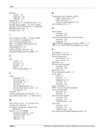
Index heatsink caution 2-36 removing 2-35 replacing 2-37 help resources ix hot-plug devices, U320 SCSI hard drive 2-4 hot-plug power supplies See power supplies hot-plug U320 SCSI hard drive See hard drive HP authorized reseller ix humidity, server 6-2 I I/O system fan assembly See fan assembly icons, symbols on equipment 2-2 iLO See Integrated lights-Out IML See Integrated Management Log input requirements 6-1 Insight Manager 7 4-1 Integrated Lights-Out (iLO) 4-2 Integrated Management Log (IML) 4-2 K kits country 1-4 fixed rail 1-4 hardware 1-2 plastics 1-2 Telco rack mounting 1-4 L LEDs front panel 5-1 network activity 5-3 network link 5-3 rear panel 5-3 rear unit identification 5-3 rear unit identification switch 2-6 system board 5-4 left bezel 1-2 locating, unit identification switches 2-5 low-profile diskette drive See diskette drive M mass storage devices See storage devices mechanical components 1-1 mechanical components exploded view, illustrated 1-1 memory See also DIMMs installation guidelines 2-31 installation order 2-31 removing 2-32 replacing 2-33 N Network Interface Controllers (NICs) LEDs, activity status 5-3 LEDs, link status 5-3 setting the operating mode 5-8 non-hot-plug devices 2-4 O optical device removing 2-14 replacing 2-15 optical device/diskette drive interface board removing 2-28 replacing 2-29 Option ROM Configuration for Arrays (ORCA) 4-3 ORCA See Option ROM Configuration for Arrays P part numbers 1-2, 1-3 parts catalog, illustrated 1-1 password protection clear and reset 5-7 how to set up 5-7 PCI blank 1-2 PCI riser board assembly removing 2-22 replacing 2-22 plastics kit 1-2 Power On/Standby switch 2-5 power supply blank 1-2 fan baffle 1-2 output power 6-2 removing 2-19 replacing 2-21 power, rated input 6-1 PPM See processor power module processor fan module removing 2-8 replacing 2-9 processor power module removing 2-38 replacing 2-39 socket locations 2-34 processors removing 2-35 replacing 2-37 socket locations 2-34 ProLiant Essentials Rapid Deployment Pack 4-3 Index-2 HP ProLiant DL360 Generation 3 Server Maintenance and Service Guide
-
 1
1 -
2
-
3
-
4
-
5
-
6
-
7
-
8
-
9
-
10
-
11
-
12
-
13
-
14
-
15
-
16
-
17
-
18
-
19
-
20
-
21
-
22
-
23
-
24
-
25
-
26
-
27
-
28
-
29
-
30
-
31
-
32
-
33
-
34
-
35
-
36
-
37
-
38
-
39
-
40
-
41
-
42
-
43
-
44
-
45
-
46
-
47
-
48
-
49
-
50
-
51
-
52
-
53
-
54
-
55
-
56
-
57
-
58
-
59
-
60
-
61
-
62
-
63
-
64
-
65
-
66
-
67
-
68
-
69
-
 70
70 -
 71
71 -
 72
72 -
 73
73 -
 74
74 -
 75
75 -
 76
76 -
 77
77
 |
 |
