HP Dv6910us HP Pavilion dv6500, dv6600, and dv6700 Entertainment PCs - Mainten - Page 62
Memory modules are designed with a notch, Remove the module
 |
UPC - 884420154020
View all HP Dv6910us manuals
Add to My Manuals
Save this manual to your list of manuals |
Page 62 highlights
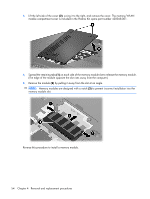
3. Lift the left side of the cover (2), swing it to the right, and remove the cover. The memory/WLAN module compartment cover is included in the Plastics Kit, spare part number 438368-001. 4. Spread the retaining tabs (1) on each side of the memory module slot to release the memory module. (The edge of the module opposite the slot rises away from the computer.) 5. Remove the module (2) by pulling it away from the slot at an angle. NOTE: Memory modules are designed with a notch (3) to prevent incorrect installation into the memory module slot. Reverse this procedure to install a memory module. 54 Chapter 4 Removal and replacement procedures
-
 1
1 -
2
-
3
-
4
-
5
-
6
-
7
-
8
-
9
-
10
-
11
-
12
-
13
-
14
-
15
-
16
-
17
-
18
-
19
-
20
-
21
-
22
-
23
-
24
-
25
-
26
-
27
-
28
-
29
-
30
-
31
-
32
-
33
-
34
-
35
-
36
-
37
-
38
-
39
-
40
-
41
-
42
-
43
-
44
-
45
-
46
-
47
-
48
-
49
-
50
-
51
-
52
-
53
-
54
-
55
-
56
-
 57
57 -
 58
58 -
 59
59 -
 60
60 -
 61
61 -
 62
62 -
 63
63 -
 64
64 -
 65
65 -
 66
66 -
 67
67 -
68
-
69
-
70
-
71
-
72
-
73
-
74
-
75
-
76
-
77
-
78
-
79
-
80
-
81
-
82
-
83
-
84
-
85
-
86
-
87
-
88
-
89
-
90
-
91
-
92
-
93
-
94
-
95
-
96
-
97
-
98
-
99
-
100
-
101
-
102
-
103
-
104
-
105
-
106
-
107
-
108
-
109
-
110
-
111
-
112
-
113
-
114
-
115
-
116
-
117
-
118
-
119
-
120
-
121
-
122
-
123
-
124
-
125
-
126
-
127
-
128
-
129
-
130
-
131
-
132
-
133
-
134
-
135
-
136
-
137
-
138
-
139
-
140
-
141
-
142
-
143
-
144
-
145
-
146
-
147
-
148
-
149
-
150
-
151
-
152
-
153
-
154
-
155
-
156
-
157
-
158
-
159
-
160
 |
 |

3
.
Lift the left side of the cover
(2)
, swing it to the right, and remove the cover. The memory/WLAN
module compartment cover is included in the Plastics Kit, spare part number 438368-001.
4
.
Spread the retaining tabs
(1)
on each side of the memory module slot to release the memory module.
(The edge of the module opposite the slot rises away from the computer.)
5
.
Remove the module
(2)
by pulling it away from the slot at an angle.
NOTE:
Memory modules are designed with a notch
(3)
to prevent incorrect installation into the
memory module slot.
Reverse this procedure to install a memory module.
54
Chapter
4
Removal and replacement procedures