HP Dv6910us HP Pavilion dv6500, dv6600, and dv6700 Entertainment PCs - Mainten - Page 80
If it is necessary to replace the microphones and cables, release the retention tabs
 |
UPC - 884420154020
View all HP Dv6910us manuals
Add to My Manuals
Save this manual to your list of manuals |
Page 80 highlights
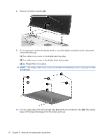
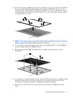
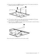
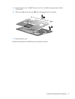
16. Remove the display hinges (3). The display hinges are available using spare part number 431395-001. 17. If it is necessary to replace the wireless antenna transceivers and cables, remove the Phillips PM2.0×3.0 screw (1) that secures each transceiver to the display enclosure. 18. Remove the wireless antenna cables from the clips (2) built into the display enclosure. 19. Detach the wireless antenna transceivers (3) from the display enclosure and remove the transceivers and cables (4). The wireless antenna transceivers and cables are available using the following spare part numbers 449727-001 (for use only with computer models equipped with an 802.11a/b/g/n WLAN module) and 431398-001 (for use only with computer models equipped with an 802.11a/ b/g or 802.11b/g WLAN module). 20. If it is necessary to replace the microphones and cables, release the retention tabs (1) built into the display enclosure that secure the microphone cables to the display enclosure 21. Remove the microphone receivers (2) from the clips in the display enclosure. 72 Chapter 4 Removal and replacement procedures
-
 1
1 -
2
-
3
-
4
-
5
-
6
-
7
-
8
-
9
-
10
-
11
-
12
-
13
-
14
-
15
-
16
-
17
-
18
-
19
-
20
-
21
-
22
-
23
-
24
-
25
-
26
-
27
-
28
-
29
-
30
-
31
-
32
-
33
-
34
-
35
-
36
-
37
-
38
-
39
-
40
-
41
-
42
-
43
-
44
-
45
-
46
-
47
-
48
-
49
-
50
-
51
-
52
-
53
-
54
-
55
-
56
-
57
-
58
-
59
-
60
-
61
-
62
-
63
-
64
-
65
-
66
-
67
-
68
-
69
-
70
-
71
-
72
-
73
-
74
-
 75
75 -
 76
76 -
 77
77 -
 78
78 -
 79
79 -
 80
80 -
 81
81 -
 82
82 -
 83
83 -
 84
84 -
 85
85 -
86
-
87
-
88
-
89
-
90
-
91
-
92
-
93
-
94
-
95
-
96
-
97
-
98
-
99
-
100
-
101
-
102
-
103
-
104
-
105
-
106
-
107
-
108
-
109
-
110
-
111
-
112
-
113
-
114
-
115
-
116
-
117
-
118
-
119
-
120
-
121
-
122
-
123
-
124
-
125
-
126
-
127
-
128
-
129
-
130
-
131
-
132
-
133
-
134
-
135
-
136
-
137
-
138
-
139
-
140
-
141
-
142
-
143
-
144
-
145
-
146
-
147
-
148
-
149
-
150
-
151
-
152
-
153
-
154
-
155
-
156
-
157
-
158
-
159
-
160
 |
 |
