HP Dv6910us HP Pavilion dv6500, dv6600, and dv6700 Entertainment PCs - Mainten - Page 91
Memory modules see, RTC battery see
 |
UPC - 884420154020
View all HP Dv6910us manuals
Add to My Manuals
Save this manual to your list of manuals |
Page 91 highlights
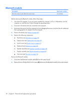
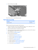
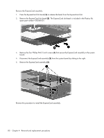
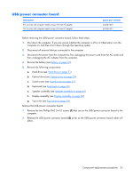
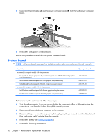
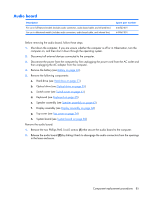
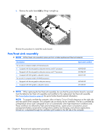
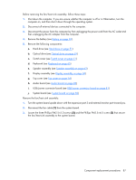
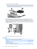
a. Hard drive (see Hard drive on page 51) b. Optical drive (see Optical drive on page 59) c. Switch cover (see Switch cover on page 61) d. Keyboard (see Keyboard on page 65) e. Speaker assembly (see Speaker assembly on page 63) f. Display assembly (see Display assembly on page 68) g. Top cover (see Top cover on page 74) h. Audio board (see Audio board on page 85) i. USB/power connector board (see USB/power connector board on page 81) When replacing the system board, be sure that the following components are removed from the defective system board and installed on the replacement system board: ● Memory modules (see Memory module on page 53) ● RTC battery (see RTC battery on page 55) ● WLAN module (see WLAN module on page 56) ● Bluetooth module (see Bluetooth module on page 78) ● ExpressCard assembly (see ExpressCard assembly on page 79) ● Fan/heat sink assembly (see Fan/heat sink assembly on page 86) ● Processor (see Processor on page 88) Remove the system board: 1. Remove the USB/power connector board cable (1) from the clips built into in the base enclosure. 2. Remove the two Phillips PM2.5×4.0 screws (2) that secure the system board to the base enclosure. Component replacement procedures 83
-
 1
1 -
2
-
3
-
4
-
5
-
6
-
7
-
8
-
9
-
10
-
11
-
12
-
13
-
14
-
15
-
16
-
17
-
18
-
19
-
20
-
21
-
22
-
23
-
24
-
25
-
26
-
27
-
28
-
29
-
30
-
31
-
32
-
33
-
34
-
35
-
36
-
37
-
38
-
39
-
40
-
41
-
42
-
43
-
44
-
45
-
46
-
47
-
48
-
49
-
50
-
51
-
52
-
53
-
54
-
55
-
56
-
57
-
58
-
59
-
60
-
61
-
62
-
63
-
64
-
65
-
66
-
67
-
68
-
69
-
70
-
71
-
72
-
73
-
74
-
75
-
76
-
77
-
78
-
79
-
80
-
81
-
82
-
83
-
84
-
85
-
 86
86 -
 87
87 -
 88
88 -
 89
89 -
 90
90 -
 91
91 -
 92
92 -
 93
93 -
 94
94 -
 95
95 -
 96
96 -
97
-
98
-
99
-
100
-
101
-
102
-
103
-
104
-
105
-
106
-
107
-
108
-
109
-
110
-
111
-
112
-
113
-
114
-
115
-
116
-
117
-
118
-
119
-
120
-
121
-
122
-
123
-
124
-
125
-
126
-
127
-
128
-
129
-
130
-
131
-
132
-
133
-
134
-
135
-
136
-
137
-
138
-
139
-
140
-
141
-
142
-
143
-
144
-
145
-
146
-
147
-
148
-
149
-
150
-
151
-
152
-
153
-
154
-
155
-
156
-
157
-
158
-
159
-
160
 |
 |
