HP Dv6910us HP Pavilion dv6500, dv6600, and dv6700 Entertainment PCs - Mainten - Page 77
CAUTION, Support the display assembly when removing the following screws. Failure to support
 |
UPC - 884420154020
View all HP Dv6910us manuals
Add to My Manuals
Save this manual to your list of manuals |
Page 77 highlights
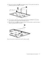
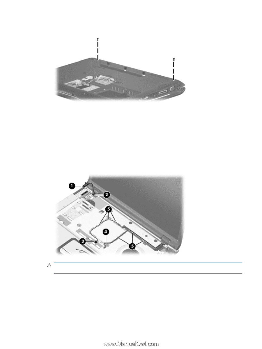
2. Remove the Phillips PM2.5×7.0 screws that secure the display assembly to the computer. 3. Turn the computer display-side up, with the front toward you. 4. Open the computer to an upright position. 5. Disconnect the following cables: (1) Display panel cable (2) Microphone cable (3) Camera cable 6. Remove the wireless antenna cables (4) from the routing channels (5) built into the top cover. CAUTION: Support the display assembly when removing the following screws. Failure to support the display assembly can result in damage to the display assembly and other computer components. 7. Remove the two Phillips PM2.5×7.0 screws (1) that secure the display assembly to the computer. Component replacement procedures 69
-
 1
1 -
2
-
3
-
4
-
5
-
6
-
7
-
8
-
9
-
10
-
11
-
12
-
13
-
14
-
15
-
16
-
17
-
18
-
19
-
20
-
21
-
22
-
23
-
24
-
25
-
26
-
27
-
28
-
29
-
30
-
31
-
32
-
33
-
34
-
35
-
36
-
37
-
38
-
39
-
40
-
41
-
42
-
43
-
44
-
45
-
46
-
47
-
48
-
49
-
50
-
51
-
52
-
53
-
54
-
55
-
56
-
57
-
58
-
59
-
60
-
61
-
62
-
63
-
64
-
65
-
66
-
67
-
68
-
69
-
70
-
71
-
 72
72 -
 73
73 -
 74
74 -
 75
75 -
 76
76 -
 77
77 -
 78
78 -
 79
79 -
 80
80 -
 81
81 -
 82
82 -
83
-
84
-
85
-
86
-
87
-
88
-
89
-
90
-
91
-
92
-
93
-
94
-
95
-
96
-
97
-
98
-
99
-
100
-
101
-
102
-
103
-
104
-
105
-
106
-
107
-
108
-
109
-
110
-
111
-
112
-
113
-
114
-
115
-
116
-
117
-
118
-
119
-
120
-
121
-
122
-
123
-
124
-
125
-
126
-
127
-
128
-
129
-
130
-
131
-
132
-
133
-
134
-
135
-
136
-
137
-
138
-
139
-
140
-
141
-
142
-
143
-
144
-
145
-
146
-
147
-
148
-
149
-
150
-
151
-
152
-
153
-
154
-
155
-
156
-
157
-
158
-
159
-
160
 |
 |
2
.
Remove the Phillips PM2.5×7.0 screws that secure the display assembly to the computer.
3
.
Turn the computer display-side up, with the front toward you.
4
.
Open the computer to an upright position.
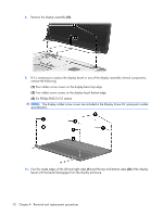
5
.
Disconnect the following cables:
(1)
Display panel cable
(2)
Microphone cable
(3)
Camera cable
6
.
Remove the wireless antenna cables
(4)
from the routing channels
(5)
built into the top cover.
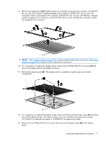
CAUTION:
Support the display assembly when removing the following screws. Failure to support
the display assembly can result in damage to the display assembly and other computer components.
7
.
Remove the two Phillips PM2.5×7.0 screws
(1)
that secure the display assembly to the computer.
Component replacement procedures
69