HP Dv6910us HP Pavilion dv6500, dv6600, and dv6700 Entertainment PCs - Mainten - Page 83
Remove the power button board cable and LED board cable., Remove the top cover
 |
UPC - 884420154020
View all HP Dv6910us manuals
Add to My Manuals
Save this manual to your list of manuals |
Page 83 highlights
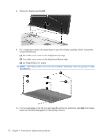
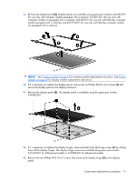
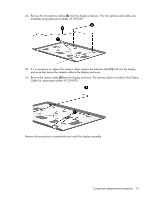
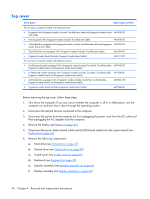
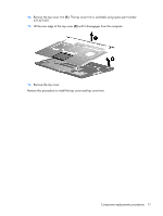
Remove the top cover: 1. Remove the power button board cable and LED button board cable from the clips (1) built into the top cover. 2. Disconnect the power button board cable (2) and the LED button board cable (3) from the low insertion force (LIF) connectors on the system board. 3. Remove the power button board cable and LED board cable. 4. Turn the computer upside down, with the front toward you. 5. Remove the nine Phillips PM2.5×7.0 screws that secure the top cover to the computer. Component replacement procedures 75
-
 1
1 -
2
-
3
-
4
-
5
-
6
-
7
-
8
-
9
-
10
-
11
-
12
-
13
-
14
-
15
-
16
-
17
-
18
-
19
-
20
-
21
-
22
-
23
-
24
-
25
-
26
-
27
-
28
-
29
-
30
-
31
-
32
-
33
-
34
-
35
-
36
-
37
-
38
-
39
-
40
-
41
-
42
-
43
-
44
-
45
-
46
-
47
-
48
-
49
-
50
-
51
-
52
-
53
-
54
-
55
-
56
-
57
-
58
-
59
-
60
-
61
-
62
-
63
-
64
-
65
-
66
-
67
-
68
-
69
-
70
-
71
-
72
-
73
-
74
-
75
-
76
-
77
-
 78
78 -
 79
79 -
 80
80 -
 81
81 -
 82
82 -
 83
83 -
 84
84 -
 85
85 -
 86
86 -
 87
87 -
 88
88 -
89
-
90
-
91
-
92
-
93
-
94
-
95
-
96
-
97
-
98
-
99
-
100
-
101
-
102
-
103
-
104
-
105
-
106
-
107
-
108
-
109
-
110
-
111
-
112
-
113
-
114
-
115
-
116
-
117
-
118
-
119
-
120
-
121
-
122
-
123
-
124
-
125
-
126
-
127
-
128
-
129
-
130
-
131
-
132
-
133
-
134
-
135
-
136
-
137
-
138
-
139
-
140
-
141
-
142
-
143
-
144
-
145
-
146
-
147
-
148
-
149
-
150
-
151
-
152
-
153
-
154
-
155
-
156
-
157
-
158
-
159
-
160
 |
 |

Remove the top cover:
1
.
Remove the power button board cable and LED button board cable from the clips
(1)
built into the
top cover.
2
.
Disconnect the power button board cable
(2)
and the LED button board cable
(3)
from the low
insertion force (LIF) connectors on the system board.
3
.
Remove the power button board cable and LED board cable.
4
.
Turn the computer upside down, with the front toward you.
5
.
Remove the nine Phillips PM2.5×7.0 screws that secure the top cover to the computer.
Component replacement procedures
75