HP Dv6910us HP Pavilion dv6500, dv6600, and dv6700 Entertainment PCs - Mainten - Page 78
Six Phillips PM2.5×5.0 screws, Flex the inside edges of the left and right sides
 |
UPC - 884420154020
View all HP Dv6910us manuals
Add to My Manuals
Save this manual to your list of manuals |
Page 78 highlights
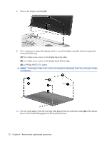
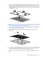
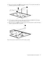
8. Remove the display assembly (2). 9. If it is necessary to replace the display bezel or any of the display assembly internal components, remove the following: (1) Four rubber screw covers on the display bezel top edge (2) Two rubber screw covers on the display bezel bottom edge (3) Six Phillips PM2.5×5.0 screws NOTE: The display rubber screw covers are included in the Display Screw Kit, spare part number 431399-001. 10. Flex the inside edges of the left and right sides (1) and the top and bottom sides (2) of the display bezel until the bezel disengages from the display enclosure. 70 Chapter 4 Removal and replacement procedures
-
 1
1 -
2
-
3
-
4
-
5
-
6
-
7
-
8
-
9
-
10
-
11
-
12
-
13
-
14
-
15
-
16
-
17
-
18
-
19
-
20
-
21
-
22
-
23
-
24
-
25
-
26
-
27
-
28
-
29
-
30
-
31
-
32
-
33
-
34
-
35
-
36
-
37
-
38
-
39
-
40
-
41
-
42
-
43
-
44
-
45
-
46
-
47
-
48
-
49
-
50
-
51
-
52
-
53
-
54
-
55
-
56
-
57
-
58
-
59
-
60
-
61
-
62
-
63
-
64
-
65
-
66
-
67
-
68
-
69
-
70
-
71
-
72
-
 73
73 -
 74
74 -
 75
75 -
 76
76 -
 77
77 -
 78
78 -
 79
79 -
 80
80 -
 81
81 -
 82
82 -
 83
83 -
84
-
85
-
86
-
87
-
88
-
89
-
90
-
91
-
92
-
93
-
94
-
95
-
96
-
97
-
98
-
99
-
100
-
101
-
102
-
103
-
104
-
105
-
106
-
107
-
108
-
109
-
110
-
111
-
112
-
113
-
114
-
115
-
116
-
117
-
118
-
119
-
120
-
121
-
122
-
123
-
124
-
125
-
126
-
127
-
128
-
129
-
130
-
131
-
132
-
133
-
134
-
135
-
136
-
137
-
138
-
139
-
140
-
141
-
142
-
143
-
144
-
145
-
146
-
147
-
148
-
149
-
150
-
151
-
152
-
153
-
154
-
155
-
156
-
157
-
158
-
159
-
160
 |
 |

8
.
Remove the display assembly
(2)
.
9
.
If it is necessary to replace the display bezel or any of the display assembly internal components,
remove the following:
(1)
Four rubber screw covers on the display bezel top edge
(2)
Two rubber screw covers on the display bezel bottom edge
(3)
Six Phillips PM2.5×5.0 screws
NOTE:
The display rubber screw covers are included in the Display Screw Kit, spare part number
431399-001.
10
.
Flex the inside edges of the left and right sides
(1)
and the top and bottom sides
(2)
of the display
bezel until the bezel disengages from the display enclosure.
70
Chapter
4
Removal and replacement procedures