HP Dv6910us HP Pavilion dv6500, dv6600, and dv6700 Entertainment PCs - Mainten - Page 90
System board
 |
UPC - 884420154020
View all HP Dv6910us manuals
Add to My Manuals
Save this manual to your list of manuals |
Page 90 highlights
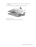
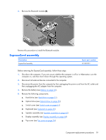
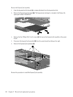
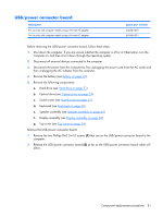
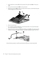
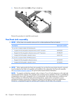
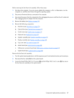
3. Disconnect the USB cable (3) and the power connector cable (4) from the USB/power connector board. 4. Remove the USB/power connector board. Reverse this procedure to install the USB/power connector board. System board NOTE: All system board spare part kits include a modem cable and replacment thermal material. Description For use only in computer models with Intel processors: ● Equipped with discrete graphics subsystem memory (includes 128 MB of discrete graphics subsystem memory) ● In full-featured models equipped with UMA graphics subsystem memory ● In defeatured models equipped with UMA graphics subsystem memory For use only in computer models with AMD processors: ● In full-featured models equipped with discrete graphics subsystem memory ● In full-featured models equipped with UMA graphics subsystem memory Spare part number 446476-001 446477-001 453769-001 449902-001 449903-001 Before removing the system board, follow these steps: 1. Shut down the computer. If you are unsure whether the computer is off or in Hibernation, turn the computer on, and then shut it down through the operating system. 2. Disconnect all external devices connected to the computer. 3. Disconnect the power from the computer by first unplugging the power cord from the AC outlet and then unplugging the AC adapter from the computer. 4. Remove the battery (see Battery on page 46). 5. Remove the following components: 82 Chapter 4 Removal and replacement procedures
-
 1
1 -
2
-
3
-
4
-
5
-
6
-
7
-
8
-
9
-
10
-
11
-
12
-
13
-
14
-
15
-
16
-
17
-
18
-
19
-
20
-
21
-
22
-
23
-
24
-
25
-
26
-
27
-
28
-
29
-
30
-
31
-
32
-
33
-
34
-
35
-
36
-
37
-
38
-
39
-
40
-
41
-
42
-
43
-
44
-
45
-
46
-
47
-
48
-
49
-
50
-
51
-
52
-
53
-
54
-
55
-
56
-
57
-
58
-
59
-
60
-
61
-
62
-
63
-
64
-
65
-
66
-
67
-
68
-
69
-
70
-
71
-
72
-
73
-
74
-
75
-
76
-
77
-
78
-
79
-
80
-
81
-
82
-
83
-
84
-
 85
85 -
 86
86 -
 87
87 -
 88
88 -
 89
89 -
 90
90 -
 91
91 -
 92
92 -
 93
93 -
 94
94 -
 95
95 -
96
-
97
-
98
-
99
-
100
-
101
-
102
-
103
-
104
-
105
-
106
-
107
-
108
-
109
-
110
-
111
-
112
-
113
-
114
-
115
-
116
-
117
-
118
-
119
-
120
-
121
-
122
-
123
-
124
-
125
-
126
-
127
-
128
-
129
-
130
-
131
-
132
-
133
-
134
-
135
-
136
-
137
-
138
-
139
-
140
-
141
-
142
-
143
-
144
-
145
-
146
-
147
-
148
-
149
-
150
-
151
-
152
-
153
-
154
-
155
-
156
-
157
-
158
-
159
-
160
 |
 |
