HP Dv6910us HP Pavilion dv6500, dv6600, and dv6700 Entertainment PCs - Mainten - Page 65
Remove the memory/WLAN module compartment cover see, Remove the WLAN module
 |
UPC - 884420154020
View all HP Dv6910us manuals
Add to My Manuals
Save this manual to your list of manuals |
Page 65 highlights
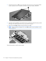
Description Spare part number Nepal, the Nether Antilles, the Netherlands, New Zealand, Nicaragua, Niger, Nigeria, Norway, Oman, Palau, Panama, Papua New Guinea, Paraguay, the People's Republic of China, Peru, the Philippines, Poland, Portugal, Qatar, the Republic of Moldova, Romania, Russia, Rwanda, Samoa, San Marino, Sao Tome & Principe, Saudi Arabia, Senegal, Serbia and Montenegro, the Seychelles, Sierra Leone, Singapore, Slovakia, Slovenia, the Solomon Islands, Somalia, South Africa, South Korea, Spain, Sri Lanka, St. Kitts & Nevis, St. Lucia, St. Vincent & Grenada, Suriname, Swaziland, Sweden, Switzerland, Taiwan, Tajikistan, Tanzania, Thailand, Togo, Tonga, Trinidad & Tobago, Tunisia, Turkey, Turkmenistan, Tuvalu, Uganda, Ukraine, the United Arab Emirates, the United Kingdom, Uruguay, Uzbekistan, Vanuatu, Venezuela, Vietnam, Yemen, Zaire, Zambia, and Zimbabwe ● For use in Japan 441090-291 Intel 802.11b/g WLAN module for use in Thailand 451861-004 Broadcom 4311AG 802.11a/b/g modules: ● For use in the United States and Canada 441075-001 ● For use in France, Germany, Italy, the Netherlands, Spain, the United Kingdom, Nordic region, 441075-002 and India Broadcom 4321AGN 802.11a/b/g/n modules: ● For use in the United States and Canada 434661-001 ● For use in France, Germany, Italy, the Netherlands, Spain, the United Kingdom, Nordic region, 434661-002 and India Before removing the WLAN module, follow these steps: 1. Shut down the computer. If you are unsure whether the computer is off or in Hibernation, turn the computer on, and then shut it down through the operating system. 2. Disconnect all external devices connected to the computer. 3. Disconnect the power from the computer by first unplugging the power cord from the AC outlet and then unplugging the AC adapter from the computer. 4. Remove the battery (see Battery on page 46). 5. Remove the memory/WLAN module compartment cover (see Memory module on page 53). Remove the WLAN module: 1. Disconnect the two WLAN antenna cables (1) from the WLAN module. NOTE: The black WLAN antenna cable is connected to the WLAN module "Main" terminal. The white WLAN antenna cable is connected to the WLAN module "Aux" terminal. NOTE: Computer models equipped with an 802.11a/b/g/n WLAN module will have an additional wireless antenna cable (2), yellow in color. 2. Remove the two Phillips PM2.0×3.0 screws (3) that secure the WLAN module to the computer. (The edge of the module opposite the slot rises away from the computer.) Component replacement procedures 57
-
 1
1 -
2
-
3
-
4
-
5
-
6
-
7
-
8
-
9
-
10
-
11
-
12
-
13
-
14
-
15
-
16
-
17
-
18
-
19
-
20
-
21
-
22
-
23
-
24
-
25
-
26
-
27
-
28
-
29
-
30
-
31
-
32
-
33
-
34
-
35
-
36
-
37
-
38
-
39
-
40
-
41
-
42
-
43
-
44
-
45
-
46
-
47
-
48
-
49
-
50
-
51
-
52
-
53
-
54
-
55
-
56
-
57
-
58
-
59
-
 60
60 -
 61
61 -
 62
62 -
 63
63 -
 64
64 -
 65
65 -
 66
66 -
 67
67 -
 68
68 -
 69
69 -
 70
70 -
71
-
72
-
73
-
74
-
75
-
76
-
77
-
78
-
79
-
80
-
81
-
82
-
83
-
84
-
85
-
86
-
87
-
88
-
89
-
90
-
91
-
92
-
93
-
94
-
95
-
96
-
97
-
98
-
99
-
100
-
101
-
102
-
103
-
104
-
105
-
106
-
107
-
108
-
109
-
110
-
111
-
112
-
113
-
114
-
115
-
116
-
117
-
118
-
119
-
120
-
121
-
122
-
123
-
124
-
125
-
126
-
127
-
128
-
129
-
130
-
131
-
132
-
133
-
134
-
135
-
136
-
137
-
138
-
139
-
140
-
141
-
142
-
143
-
144
-
145
-
146
-
147
-
148
-
149
-
150
-
151
-
152
-
153
-
154
-
155
-
156
-
157
-
158
-
159
-
160
 |
 |
