HP Dv6910us HP Pavilion dv6500, dv6600, and dv6700 Entertainment PCs - Mainten - Page 70
the power button board., Release the ZIF connector
 |
UPC - 884420154020
View all HP Dv6910us manuals
Add to My Manuals
Save this manual to your list of manuals |
Page 70 highlights
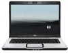
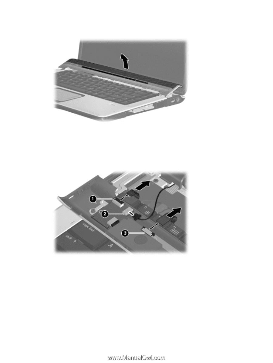
4. Lift the rear edge of the switch cover and swing it forward until it rests on the keyboard. 5. Release the zero insertion force (ZIF) connector (1) to which the power button board is connected, and disconnect the cable from the power button board. 6. Disconnect the microphone cable (2) from the power button board. 7. Release the ZIF connector (3) to which the LED board is connected and disconnect the cable from the power button board. 8. Remove the switch cover. Reverse this procedure to install the switch cover. 62 Chapter 4 Removal and replacement procedures
-
 1
1 -
2
-
3
-
4
-
5
-
6
-
7
-
8
-
9
-
10
-
11
-
12
-
13
-
14
-
15
-
16
-
17
-
18
-
19
-
20
-
21
-
22
-
23
-
24
-
25
-
26
-
27
-
28
-
29
-
30
-
31
-
32
-
33
-
34
-
35
-
36
-
37
-
38
-
39
-
40
-
41
-
42
-
43
-
44
-
45
-
46
-
47
-
48
-
49
-
50
-
51
-
52
-
53
-
54
-
55
-
56
-
57
-
58
-
59
-
60
-
61
-
62
-
63
-
64
-
 65
65 -
 66
66 -
 67
67 -
 68
68 -
 69
69 -
 70
70 -
 71
71 -
 72
72 -
 73
73 -
 74
74 -
 75
75 -
76
-
77
-
78
-
79
-
80
-
81
-
82
-
83
-
84
-
85
-
86
-
87
-
88
-
89
-
90
-
91
-
92
-
93
-
94
-
95
-
96
-
97
-
98
-
99
-
100
-
101
-
102
-
103
-
104
-
105
-
106
-
107
-
108
-
109
-
110
-
111
-
112
-
113
-
114
-
115
-
116
-
117
-
118
-
119
-
120
-
121
-
122
-
123
-
124
-
125
-
126
-
127
-
128
-
129
-
130
-
131
-
132
-
133
-
134
-
135
-
136
-
137
-
138
-
139
-
140
-
141
-
142
-
143
-
144
-
145
-
146
-
147
-
148
-
149
-
150
-
151
-
152
-
153
-
154
-
155
-
156
-
157
-
158
-
159
-
160
 |
 |
4
.
Lift the rear edge of the switch cover and swing it forward until it rests on the keyboard.
5
.
Release the zero insertion force (ZIF) connector
(1)
to which the power button board is connected,
and disconnect the cable from the power button board.
6
.
Disconnect the microphone cable
(2)
from the power button board.
7
.
Release the ZIF connector
(3)
to which the LED board is connected and disconnect the cable from
the power button board.
8
.
Remove the switch cover.
Reverse this procedure to install the switch cover.
62
Chapter
4
Removal and replacement procedures