HP Mini CQ10-100 Compaq Mini CQ10 Notebook PC - Maintenance and Service Guide
HP Mini CQ10-100 - PC Manual
 |
View all HP Mini CQ10-100 manuals
Add to My Manuals
Save this manual to your list of manuals |
HP Mini CQ10-100 manual content summary:
- HP Mini CQ10-100 | Compaq Mini CQ10 Notebook PC - Maintenance and Service Guide - Page 1
Compaq Mini CQ10 Notebook PC Maintenance and Service Guide - HP Mini CQ10-100 | Compaq Mini CQ10 Notebook PC - Maintenance and Service Guide - Page 2
the U.S. and other countries. Microsoft and Windows are U.S. registered trademarks of Microsoft Corporation. HP products and services are set forth in the express warranty statements accompanying such products and services. Nothing herein should be construed as constituting an additional warranty. HP - HP Mini CQ10-100 | Compaq Mini CQ10 Notebook PC - Maintenance and Service Guide - Page 3
, such as an adjoining optional printer, or a soft surface, such as pillows or rugs or clothing, to block airflow. Also, do not allow the AC adapter to contact the skin or a soft surface, such as pillows or rugs or clothing, during operation. The computer and the AC - HP Mini CQ10-100 | Compaq Mini CQ10 Notebook PC - Maintenance and Service Guide - Page 4
iv Safety Warning Notice - HP Mini CQ10-100 | Compaq Mini CQ10 Notebook PC - Maintenance and Service Guide - Page 5
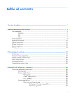
components ...10 Left-side components ...11 Display components ...12 Bottom components ...13 Wireless antennas ...14 3 Illustrated parts catalog 15 Service tag ...15 Computer major components 16 Display assembly subcomponents 20 Mass storage devices ...22 Miscellaneous parts ...23 Sequential part - HP Mini CQ10-100 | Compaq Mini CQ10 Notebook PC - Maintenance and Service Guide - Page 6
Memory module ...37 Keyboard ...39 RTC battery ...42 Mass storage devices 43 Hard drive 44 Top cover ...45 WLAN module ...48 WWAN module ...51 USB/audio board 53 DC connector/power the Setup Utility 70 Displaying system information 70 Restoring default settings in the Setup Utility 70 Exiting - HP Mini CQ10-100 | Compaq Mini CQ10 Notebook PC - Maintenance and Service Guide - Page 7
7 Backup and recovery ...81 Windows XP backup and recovery 82 Backing up your information 82 Performing 85 External monitor ...86 RJ-45 (network) ...87 Universal Serial Bus ...88 9 Power cord set requirements 89 Requirements for all countries and regions 89 Requirements for specific countries - HP Mini CQ10-100 | Compaq Mini CQ10 Notebook PC - Maintenance and Service Guide - Page 8
viii - HP Mini CQ10-100 | Compaq Mini CQ10 Notebook PC - Maintenance and Service Guide - Page 9
1 Product description Category Product name Processor Chipset Graphics Panels Memory Mass storage devices Optical drive Diskette drive Audio/Visual Description Compaq Mini CQ10 Intel Atom N270 1.6-GHz processor, 512-KB Level 2 cache, 533-MHz front-side bus (FSB) Northbridge: 945GSE; 533-MHz bus - HP Mini CQ10-100 | Compaq Mini CQ10 Notebook PC - Maintenance and Service Guide - Page 10
Digital Media Slot with push-push insert/eject port supporting: ● Memory Stick (MS) ● MS/Pro ● MultiMediaCard (MMC) ● Secure Digital High Capacity (SDHC) memory card ● xD-Picture Card Two Mini Card slots: ● Full-size Mini Card slot ● Half-size Mini Card slot Audio-in/out (microphone/stereo headphone - HP Mini CQ10-100 | Compaq Mini CQ10 Notebook PC - Maintenance and Service Guide - Page 11
(55-Wh) 2.55-Ah, 6-hour target life 3-cell Li-ion battery (28-Wh) 2.55-Ah , 3-hour target life Supports HP Kensington Security Lock Preinstalled: Windows XP Home Edition SP3 End-user replaceable parts: AC adapter Battery (system) Keyboard Hard drive (located under the keyboard) Memory modules 3 - HP Mini CQ10-100 | Compaq Mini CQ10 Notebook PC - Maintenance and Service Guide - Page 12
2 External component identification Components included with the computer may vary by region and model. The illustrations in this chapter identify the standard features on most computer models. Top components 4 Chapter 2 External component identification - HP Mini CQ10-100 | Compaq Mini CQ10 Notebook PC - Maintenance and Service Guide - Page 13
TouchPad Component Description (1) Left TouchPad button* Functions like the left button on an external mouse. (2) TouchPad* Moves the pointer and selects or activates items on the screen. (3) TouchPad scroll zone Scrolls up or down. (4) Right TouchPad button* Functions like the right - HP Mini CQ10-100 | Compaq Mini CQ10 Notebook PC - Maintenance and Service Guide - Page 14
Light Component Caps lock light Description On: Caps lock is on. 6 Chapter 2 External component identification - HP Mini CQ10-100 | Compaq Mini CQ10 Notebook PC - Maintenance and Service Guide - Page 15
Component (1) Function keys (2) fn key (3) Windows® logo key (4) Windows applications key Description Execute frequently used system functions when pressed in combination with a function key. Displays the Windows Start menu. Displays a shortcut menu for items beneath the pointer. Top components - HP Mini CQ10-100 | Compaq Mini CQ10 Notebook PC - Maintenance and Service Guide - Page 16
to exit Standby. ● When the computer is in Hibernation, briefly slide the switch to exit Hibernation. If the computer has stopped responding and Windows shutdown procedures are ineffective, slide and hold the power switch for at least 5 seconds to turn off the computer. To learn more about your - HP Mini CQ10-100 | Compaq Mini CQ10 Notebook PC - Maintenance and Service Guide - Page 17
Component (5) Wireless light (6) Wireless switch Description ● Blue: An integrated wireless device, such as a wireless local area network (WLAN) device, is on. ● Amber: All wireless devices are off. Turns the wireless feature on or off, but does not establish a wireless connection. NOTE: A - HP Mini CQ10-100 | Compaq Mini CQ10 Notebook PC - Maintenance and Service Guide - Page 18
port (4) RJ-45 (network) jack Description Connect optional USB devices. Supports the following optional digital card formats: ● Memory Stick (MS) ● MS/Pro ● MultiMediaCard (MMC) ● Secure Digital High Capacity (SDHC) Memory Card ● xD-Picture card Connects an optional external display, such as - HP Mini CQ10-100 | Compaq Mini CQ10 Notebook PC - Maintenance and Service Guide - Page 19
, but it may not prevent the computer from being mishandled or stolen. Connects an AC adapter. On: The computer is connected to external power. Off: The computer is not connected to external power. Enables airflow to cool internal components. NOTE: The computer fan starts up automatically to cool - HP Mini CQ10-100 | Compaq Mini CQ10 Notebook PC - Maintenance and Service Guide - Page 20
display switch (3) Webcam (4) Webcam light (5) Internal microphone Description Produce sound. Turns off the display if the display is closed while the power is on. NOTE: The display switch is not visible from the outside of the computer. Captures still photographs and videos. NOTE: To - HP Mini CQ10-100 | Compaq Mini CQ10 Notebook PC - Maintenance and Service Guide - Page 21
Bottom components Component (1) Battery bay (2) Battery release latches (2) (3) Vent (4) Memory module compartment Description Holds the battery. Release the battery from the battery bay. Enables airflow to cool internal components. NOTE: The computer fan starts up - HP Mini CQ10-100 | Compaq Mini CQ10 Notebook PC - Maintenance and Service Guide - Page 22
to the section of the Regulatory, Safety and Environmental Notices that applies to your country or region. To access these notices, click Start > Help and Support > User Guides. 14 Chapter 2 External component identification - HP Mini CQ10-100 | Compaq Mini CQ10 Notebook PC - Maintenance and Service Guide - Page 23
the product's hardware components. The part number helps a service technician to determine what components and parts are needed. (4) Model description: This is the alphanumeric identifier used to locate documents, drivers, and support for the computer. (5) Warranty period: This number describes - HP Mini CQ10-100 | Compaq Mini CQ10 Notebook PC - Maintenance and Service Guide - Page 24
Computer major components Item (1) Description Display assembly Includes 1 webcam, 1 microphone, 2 speakers, and 2 WLAN antennas/cables; WWAN antennas/cables on select models See Display assembly subcomponents on page 20 for a comprehensive list of display assembly components. ● 25.7-cm (10.1-inch - HP Mini CQ10-100 | Compaq Mini CQ10 Notebook PC - Maintenance and Service Guide - Page 25
Item Description ● 25.7-cm (10.1-inch), WSVGA, AntiGlare display assembly for use with WWAN option (2) Keyboard ● For use in Brazil ● For use in the Czech Republic ● For use in Europe ● For use in Finland, Norway, and Sweden ● For use in France ● - HP Mini CQ10-100 | Compaq Mini CQ10 Notebook PC - Maintenance and Service Guide - Page 26
board Plastics/actuator kit Power switch and wireless switch actuators Memory module compartment cover Bezel for Digital Media slot Wireless modules 599188-001 537612-001 WLAN module Broadcom 4312G 802.11b/g WiFi and 2070 Bluetooth 2.1+EDR Combo Adapter (BT3.0+HS ready) Broadcom 43225 802.11b - HP Mini CQ10-100 | Compaq Mini CQ10 Notebook PC - Maintenance and Service Guide - Page 27
(FSB) 594804-001 ● Intel Atom N270 1.6-GHz processor, 512-KB Level 2 cache, 533-MHz front-side bus (FSB) for use with WWAN option 599187-001 Memory module ● 1024-MB, PC2-6400, DDR2, 533-MHz 598861-001 ● 1024-MB, PC2-6400, DDR2, 533-MHz, for use with WWAN option 600131-001 Base - HP Mini CQ10-100 | Compaq Mini CQ10 Notebook PC - Maintenance and Service Guide - Page 28
Display assembly subcomponents Item Description (1) EMI shield and hinge covers (2) Display bezel with logo for use with webcam and microphone (3) Display hinge kit (Includes left and right display panel hinges) (4) Speaker assembly Includes 2 speakers, cable, and housing (5) Display panel 25.7-cm - HP Mini CQ10-100 | Compaq Mini CQ10 Notebook PC - Maintenance and Service Guide - Page 29
Item Description (9) WWAN antenna assembly (optional) (10) Display back cover with logo Display screw kit (not illustrated) Includes 14 PM2.0×3.0×4.0×0.4T screws Spare part number 538022-001 594808-001 538510-001 Display assembly subcomponents 21 - HP Mini CQ10-100 | Compaq Mini CQ10 Notebook PC - Maintenance and Service Guide - Page 30
Mass storage devices NOTE: Each hard drive spare part kit includes a mounting bracket. Item Description Spare part number (1) Hard drive, 160 GB, 5400 RPM 594809-001 Hard drive mounting kit (not illustrated, includes mounting bracket and 4 PM3.0×3.0×4.5 screws) 537641-001 22 Chapter 3 - HP Mini CQ10-100 | Compaq Mini CQ10 Notebook PC - Maintenance and Service Guide - Page 31
Miscellaneous parts Description 30-W, 3-pin AC adapter Power cords, 3-pin, 1.83m ● For use in Argentina ● For use in Brazil ● For use in Denmark ● For use in Europe ● For use in Israel ● For use - HP Mini CQ10-100 | Compaq Mini CQ10 Notebook PC - Maintenance and Service Guide - Page 32
cord, 3-pin, 1.83m, for use in South Africa 490371-BB1 Power cord, 3-pin, 1.83m, for use in Israel 490371-D01 Power cord, 3-pin, 1.83m, for use in Argentina 496813-001 30-W, 3-pin AC adapter 504593-003 Broadcom 4312G 802.11b/g WiFi Adapter for use for use in Canada, the Cayman Islands, Guam - HP Mini CQ10-100 | Compaq Mini CQ10 Notebook PC - Maintenance and Service Guide - Page 33
802.11b/g/n 1x1 WiFi Adapter for use in Afghanistan, Keyboard for use in the United Kingdom Keyboard for use in Germany Keyboard for use in France Keyboard for use in Italy Keyboard for use in Spain Keyboard for use in French Canada Keyboard for use in Portugal Keyboard for use in Turkey Keyboard - HP Mini CQ10-100 | Compaq Mini CQ10 Notebook PC - Maintenance and Service Guide - Page 34
-001 Keyboard for use in Finland, Norway, and Sweden Keyboard for ) Display bezel with Compaq logo for use with EDR Combo Adapter Display cable Broadcom 43225 802.11b/g/n 2x2 WiFi Adapter System board, Intel Atom N270 two 4-ohm speakers, cable, and housing) Memory module, 1024-MB, PC2-6400, DDR2, - HP Mini CQ10-100 | Compaq Mini CQ10 Notebook PC - Maintenance and Service Guide - Page 35
600125-001 600131-001 Display, 25.7-cm (10.1-inch), WSVGA, AntiGlare Memory module, 1024-MB, PC2-6400, DDR2, 533-MHz, for use with WWAN option Sequential part number listing 27 - HP Mini CQ10-100 | Compaq Mini CQ10 Notebook PC - Maintenance and Service Guide - Page 36
plastic parts. Use care when handling the plastic parts. Apply pressure only at the points designated in the maintenance instructions. Cables and connectors CAUTION: When servicing the computer, be sure that cables are placed in their proper locations during the reassembly process. Improper cable - HP Mini CQ10-100 | Compaq Mini CQ10 Notebook PC - Maintenance and Service Guide - Page 37
Drive handling CAUTION: Drives are fragile components that must be handled with care. To prevent damage to the computer, damage to a drive, or loss of information, observe these precautions: Before removing or inserting a hard drive, shut down the computer. If you are unsure whether the computer is - HP Mini CQ10-100 | Compaq Mini CQ10 Notebook PC - Maintenance and Service Guide - Page 38
some protection, but in many cases, ESD contains enough power to alter device parameters or melt silicon junctions. A discharge V 2,000 V 11,500 V 14,500 V 26,500 V 21,000 V 15,000 V 5,000 V 800 V 700 V 4,000 V 5,000 V 20,000 V 11,000 V 55% 7,500 V 3,000 V 400 V 400 V 2,000 V 3,500 V 7,000 V - HP Mini CQ10-100 | Compaq Mini CQ10 Notebook PC - Maintenance and Service Guide - Page 39
material. ● Use a wrist strap connected to a properly grounded work surface and use properly grounded tools and equipment. ● Use conductive field service tools, such as cutters, screwdrivers, and vacuums. ● When fixtures must directly contact dissipative surfaces, use fixtures made only of static - HP Mini CQ10-100 | Compaq Mini CQ10 Notebook PC - Maintenance and Service Guide - Page 40
(heel, toe, or boot straps) can be used at standing workstations and are compatible with most types of shoes or boots. On conductive floors or mats with hard ties to the ground ● Field service kits ● Static awareness labels ● Material-handling 500 V 7,500 V 5,000 V 32 Chapter - HP Mini CQ10-100 | Compaq Mini CQ10 Notebook PC - Maintenance and Service Guide - Page 41
the product's hardware components. The part number helps a service technician to determine what components and parts are needed. (4) Model description: This is the alphanumeric identifier used to locate documents, drivers, and support for the computer. (5) Warranty period: This number describes - HP Mini CQ10-100 | Compaq Mini CQ10 Notebook PC - Maintenance and Service Guide - Page 42
Computer feet The computer feet are adhesive-backed rubber pads, tethered to the base enclosure. Description Rubber kit Spare part number 537618-001 34 Chapter 4 Removal and replacement procedures - HP Mini CQ10-100 | Compaq Mini CQ10 Notebook PC - Maintenance and Service Guide - Page 43
the operating system. 2. Disconnect all external devices connected to the computer. 3. Disconnect the power from the computer by first unplugging the power cord from the AC outlet and then unplugging the AC adapter from the computer. Remove the battery: 1. Turn the computer upside down on a flat - HP Mini CQ10-100 | Compaq Mini CQ10 Notebook PC - Maintenance and Service Guide - Page 44
the operating system. 2. Disconnect all external devices connected to the computer. 3. Disconnect the power from the computer by first unplugging the power cord from the AC outlet and then unplugging the AC adapter from the computer. 4. Remove the battery (see Battery on page 35). Remove the SIM - HP Mini CQ10-100 | Compaq Mini CQ10 Notebook PC - Maintenance and Service Guide - Page 45
computer by first unplugging the power cord from the AC outlet and then unplugging the AC adapter from the computer. 4. Remove the battery (see Battery on page 35). 5. If your computer has WWAN capability, remove the SIM (see SIM on page 36). Remove the memory module: 1. Loosen the 2 Phillips PM2 - HP Mini CQ10-100 | Compaq Mini CQ10 Notebook PC - Maintenance and Service Guide - Page 46
4. Remove the memory module (2) by pulling the module away from the slot at an angle. NOTE: Memory modules are designed with a notch (3) to prevent incorrect insertion into the memory module slot. Reverse this procedure to install a memory module. 38 Chapter 4 Removal and replacement procedures - HP Mini CQ10-100 | Compaq Mini CQ10 Notebook PC - Maintenance and Service Guide - Page 47
535689-221 535689-031 535689-001 535689-141 535689-B31 Before removing the keyboard, follow these steps: 1. Shut down the computer. If you are unsure 3. Disconnect the power from the computer by first unplugging the power cord from the AC outlet and then unplugging the AC adapter from the computer - HP Mini CQ10-100 | Compaq Mini CQ10 Notebook PC - Maintenance and Service Guide - Page 48
the computer. 2. Turn the computer right-side up, and then open the display as far as possible. 3. Turn the computer upside down, and locate the keyboard release access on the bottom of the computer, inside the battery bay. 4. Insert a flexible tool into the opening, and then press inward to release - HP Mini CQ10-100 | Compaq Mini CQ10 Notebook PC - Maintenance and Service Guide - Page 49
rests on the display assembly (2). 7. Release the zero insertion force (ZIF) connector (1) to which the keyboard cable is attached. 8. Disconnect the cable (2), and then remove the keyboard. 9. Remove the keyboard. Reverse this procedure to install the keyboard. Component replacement procedures 41 - HP Mini CQ10-100 | Compaq Mini CQ10 Notebook PC - Maintenance and Service Guide - Page 50
computer by first unplugging the power cord from the AC outlet and then unplugging the AC adapter from the computer. 4. Remove the battery (see Battery on page 35). 5. If your computer has WWAN capability, remove the SIM (see SIM on page 36). 6. Remove the Keyboard (see Keyboard on page 39). Remove - HP Mini CQ10-100 | Compaq Mini CQ10 Notebook PC - Maintenance and Service Guide - Page 51
the computer by first unplugging the power cord from the AC outlet and then unplugging the AC adapter from the computer. 4. Remove the battery (see Battery on page 35). 5. If your computer has WWAN capability, remove the SIM (see SIM on page 36). 6. Remove the keyboard (see Keyboard on page 39). To - HP Mini CQ10-100 | Compaq Mini CQ10 Notebook PC - Maintenance and Service Guide - Page 52
Hard drive 1. Remove the 4 Phillips PM3.0×3.0 screws (1) that secure the hard drive bracket to the hard drive. 2. Using the Mylar tab, lift the bracket (2) away from the hard drive. Reverse this procedure to install a hard drive. 44 Chapter 4 Removal and replacement procedures - HP Mini CQ10-100 | Compaq Mini CQ10 Notebook PC - Maintenance and Service Guide - Page 53
the power cord from the AC outlet and then unplugging the AC adapter from the computer. 4. Remove the battery (see Battery on page 35). 5. If your computer has WWAN capability, remove the SIM (see SIM on page 36). 6. Remove the memory module (see Memory module on page 37). 7. Remove the keyboard - HP Mini CQ10-100 | Compaq Mini CQ10 Notebook PC - Maintenance and Service Guide - Page 54
6. Remove the 8 Phillips PM2.5×6.0 screws that secure the top cover to the base enclosure. 7. Lift the inside edge of the top cover (1) and swing it up. Then slide the top cover back slightly to rest against the display assembly (2) at an angle. 8. Release the ZIF connector (1) to which the TouchPad - HP Mini CQ10-100 | Compaq Mini CQ10 Notebook PC - Maintenance and Service Guide - Page 55
9. Disconnect the TouchPad button board cable (2) from the system board, and then remove the top cover. Reverse this procedure to install the top cover. Component replacement procedures 47 - HP Mini CQ10-100 | Compaq Mini CQ10 Notebook PC - Maintenance and Service Guide - Page 56
Description Spare part number Broadcom 4312G 802.11b/g WiFi and 2070 Bluetooth 2.1+EDR Combo Adapter 575920-001 Broadcom 43225 802.11b/g/n 2x2 WiFi Adapter 593837-001 Atheros 9285G 802.11b/g/n 1x1 WiFi Adapter ● For use in Canada, the Cayman Islands, Guam, Puerto Rico, the U.S. Virgin Islands - HP Mini CQ10-100 | Compaq Mini CQ10 Notebook PC - Maintenance and Service Guide - Page 57
warning message, remove the module to restore computer functionality, and then contact technical support through Help and Support. Before removing the WLAN module, 3. Disconnect power from the computer by first unplugging the power cord from the AC outlet and then unplugging the AC adapter from the - HP Mini CQ10-100 | Compaq Mini CQ10 Notebook PC - Maintenance and Service Guide - Page 58
5. If your computer has WWAN capability, remove the SIM (see SIM on page 36). 6. Remove the following components: a. Keyboard (see Keyboard on page 39) b. Hard drive (see Mass storage devices on page 43) c. Top cover (see Top cover on page 45) Remove the WLAN module: 1. Remove - HP Mini CQ10-100 | Compaq Mini CQ10 Notebook PC - Maintenance and Service Guide - Page 59
restore computer functionality, and then contact technical support power cord from the AC outlet and then unplugging the AC adapter from the computer. 4. Remove the battery (see Battery on page 35). 5. Remove the SIM (see SIM on page 36). 6. Remove the following components: a. Keyboard (see Keyboard - HP Mini CQ10-100 | Compaq Mini CQ10 Notebook PC - Maintenance and Service Guide - Page 60
3. Remove the WWAN module (3) by pulling the module away from the slot at an angle. Reverse this procedure to install the WWAN module. 52 Chapter 4 Removal and replacement procedures - HP Mini CQ10-100 | Compaq Mini CQ10 Notebook PC - Maintenance and Service Guide - Page 61
first unplugging the power cord from the AC outlet and then unplugging the AC Adapter from the computer. 4. Remove the battery (see Battery on page 35). 5. If your computer has WWAN capability, remove the SIM (see SIM on page 36). 6. Remove the following components: a. Keyboard (see Keyboard on page - HP Mini CQ10-100 | Compaq Mini CQ10 Notebook PC - Maintenance and Service Guide - Page 62
first unplugging the power cord from the AC outlet and then unplugging the AC adapter from the computer. 4. Remove the battery (see Battery on page 35). 5. If your computer has WWAN capability, remove the SIM (see SIM on page 36). 6. Remove the following components: a. Keyboard (see Keyboard on page - HP Mini CQ10-100 | Compaq Mini CQ10 Notebook PC - Maintenance and Service Guide - Page 63
first unplugging the power cord from the AC outlet and then unplugging the AC adapter from the computer. 4. Remove the battery (see Battery on page 35). 5. If your computer has WWAN capability, remove the SIM (see SIM on page 36). 6. Remove the following components: a. Keyboard (see Keyboard on page - HP Mini CQ10-100 | Compaq Mini CQ10 Notebook PC - Maintenance and Service Guide - Page 64
3. Remove the fan (3). Reverse this procedure to install the fan. 56 Chapter 4 Removal and replacement procedures - HP Mini CQ10-100 | Compaq Mini CQ10 Notebook PC - Maintenance and Service Guide - Page 65
first unplugging the power cord from the AC outlet and then unplugging the AC adapter from the computer. 4. Remove the battery (see Battery on page 35). 5. If your computer has WWAN capability, remove the SIM (see SIM on page 36). 6. Remove the following components: a. Keyboard (see Keyboard on page - HP Mini CQ10-100 | Compaq Mini CQ10 Notebook PC - Maintenance and Service Guide - Page 66
2. Remove the heat sink assembly (2). NOTE: Due to the adhesive quality of the thermal material located between the heat sink assembly and system board components, it may be necessary to move the heat sink assembly from side to side to detach the assembly. NOTE: The thermal material must be - HP Mini CQ10-100 | Compaq Mini CQ10 Notebook PC - Maintenance and Service Guide - Page 67
first unplugging the power cord from the AC outlet and then unplugging the AC adapter from the computer. 4. Remove the battery (see Battery on page 35). 5. If your computer has WWAN capability, remove the SIM (see SIM on page 36). 6. Remove the following components: a. Keyboard (see Keyboard on page - HP Mini CQ10-100 | Compaq Mini CQ10 Notebook PC - Maintenance and Service Guide - Page 68
cable (4) Speaker cable (5) WLAN cables (6) WWAN cables (select models only) 3. Remove the 2 Phillips PM1.6×2.0 screws (1) that secure the actuators for the power switch and wireless on/off switch to the system board. 4. Remove the actuators (2). 60 Chapter 4 Removal and replacement procedures - HP Mini CQ10-100 | Compaq Mini CQ10 Notebook PC - Maintenance and Service Guide - Page 69
5. Remove the 3 Phillips PM2.5×4.0 screws that secure the system board to the base enclosure. 6. Grasp the system board at the midpoint of the left side (1), and lift it up. 7. Pull the system board (2) out to the left at an angle to remove it. 8. Remove the system board. Reverse the procedure to - HP Mini CQ10-100 | Compaq Mini CQ10 Notebook PC - Maintenance and Service Guide - Page 70
first unplugging the power cord from the AC outlet and then unplugging the AC adapter from the computer. 4. Remove the battery (see Battery on page 35). 5. If your computer has WWAN capability, remove the SIM (see SIM on page 36). 6. Remove the following components: a. Keyboard (see Keyboard on page - HP Mini CQ10-100 | Compaq Mini CQ10 Notebook PC - Maintenance and Service Guide - Page 71
Display panel cable (3) Microphone cable (4) Speaker cable (5) WLAN cables (6) WWAN cables (select models only) CAUTION: Support the display assembly when removing the following screws. Failure to support the display assembly can result in damage to the display assembly and other computer components - HP Mini CQ10-100 | Compaq Mini CQ10 Notebook PC - Maintenance and Service Guide - Page 72
4. Remove the display assembly (3). 5. If it is necessary to replace the display bezel, perform the following steps: a. Remove the display hinge covers (1). b. Flex the inside edges of the top and bottom (2), and then the left and right sides (3) of the display bezel until the bezel disengages from - HP Mini CQ10-100 | Compaq Mini CQ10 Notebook PC - Maintenance and Service Guide - Page 73
6. If it is necessary to replace the display panel, perform the following steps: a. Remove the 7 Phillips PM2.0×3.0 screws that secure the display panel to the display enclosure. b. Lift the display panel up from the display enclosure (1). c. Disconnect the webcam cable (2) from the system board (2) - HP Mini CQ10-100 | Compaq Mini CQ10 Notebook PC - Maintenance and Service Guide - Page 74
b. Remove the speaker assembly (2). 8. If it is necessary to replace the display hinges, perform the following steps: a. Remove the 2 Phillips PM2.0×3.0 screws (1) that secure each hinge to the display enclosure. b. Remove the hinges (2). 9. If it is necessary to replace the display panel cable, - HP Mini CQ10-100 | Compaq Mini CQ10 Notebook PC - Maintenance and Service Guide - Page 75
b. Disconnect the display panel cable (2). 10. If it is necessary to replace the webcam module, perform the following steps: a. Disconnect the webcam cable (1) from the webcam. b. Remove the webcam (2). 11. If it is necessary to replace the microphone receiver, perform the following steps: a. - HP Mini CQ10-100 | Compaq Mini CQ10 Notebook PC - Maintenance and Service Guide - Page 76
b. Pull the receiver through the tabs (2), and remove the microphone receiver (3). 12. If it is necessary to replace the wireless antenna transceivers and cables, detach the cables from the adhesive (1) that secures them to the display enclosure, and then remove the cables (2). Reverse this - HP Mini CQ10-100 | Compaq Mini CQ10 Notebook PC - Maintenance and Service Guide - Page 77
5 Setup Utility Starting Setup Utility Setup Utility is a ROM-based information and customization utility that can be used even when your Windows operating system is not working. The utility reports information about the computer and provides settings for startup, security, and other preferences. To - HP Mini CQ10-100 | Compaq Mini CQ10 Notebook PC - Maintenance and Service Guide - Page 78
in the Setup Utility Because Setup Utility is not Windows based, it does not support the TouchPad. Navigation and selection are by keystroke. , and then press enter. Restoring default settings in the Setup Utility The following procedure explains how to restore the Setup Utility default settings. - HP Mini CQ10-100 | Compaq Mini CQ10 Notebook PC - Maintenance and Service Guide - Page 79
time and date. ● View identification information about the computer. ● View specification information about the processor, memory size, and system BIOS. Security menu Select Administrator password Power-On Password To do this Enter, change, or delete an administrator password. Enter, change, or - HP Mini CQ10-100 | Compaq Mini CQ10 Notebook PC - Maintenance and Service Guide - Page 80
Floppy ◦ USB CD/DVD ROM Drive ◦ USB flash drive ◦ USB Hard drive ◦ USB Card Reader ◦ Network adapter NOTE: Only the devices attached to the system will appear in the boot order menu. To do this Run a comprehensive self-test on the hard drive. Run a diagnostic test on the system memory. 72 Chapter - HP Mini CQ10-100 | Compaq Mini CQ10 Notebook PC - Maintenance and Service Guide - Page 81
Depth 16.67 cm 6.56 in Width Height Weight 25.7cm (10.1-in.) LCD, equipped with a 3-cell battery, hard drive, 1-GB memory, WLAN module, and 2 wireless antennas Input power 26.17 cm 2.52 cm 1.17 kg 10.30 in 0.99 in 2.57 lb Operating voltage Operating current Temperature Operating Nonoperating - HP Mini CQ10-100 | Compaq Mini CQ10 Notebook PC - Maintenance and Service Guide - Page 82
of colors Contrast ratio Brightness Pixel resolution Pitch Format Configuration Backlight Character display Total power consumption Viewing angle 262,144 400:1 (typical) 200 nits (typical) 0.2175 × 0.2175 mm 1024 × 600 RGB vertical stripe Edge lit 80 × 25 3.0 W +/-40° horizontal, +20/-40° vertical - HP Mini CQ10-100 | Compaq Mini CQ10 Notebook PC - Maintenance and Service Guide - Page 83
Dimensions Height Width Weight Interface type 9.5 mm 70 mm 101 g SATA Transfer rate 100 MB/sec Security Seek times (typical read, including setting) Single track Average Maximum NOTE: Certain restrictions and exclusions apply. Contact technical support for details. Hard drive specifications 75 - HP Mini CQ10-100 | Compaq Mini CQ10 Notebook PC - Maintenance and Service Guide - Page 84
System DMA specifications Hardware DMA DMA0 DMA1* DMA2* DMA3 DMA4 System function Not applicable Not applicable Not applicable Not applicable Direct memory access controller 76 Chapter 6 Specifications - HP Mini CQ10-100 | Compaq Mini CQ10 Notebook PC - Maintenance and Service Guide - Page 85
timer Standard 101-/102-Key or Microsoft® Natural PS/2 Keyboard System CMOS/real-time clock Microsoft ACPI-compliant system Intel 82801G (ICH7 Family) USB Universal Host Controller-27CB Microsoft UAA Bus Driver for High Definition Audio Mobile Intel 945 Express Chipset Family Intel 82801G (ICH7 - HP Mini CQ10-100 | Compaq Mini CQ10 Notebook PC - Maintenance and Service Guide - Page 86
System speaker Microsoft ACPI-Compliant Embedded Controller Motherboard resources Standard 101-/102-Key or Microsoft Natural PS/2 Keyboard Motherboard resources Microsoft ACPI-Compliant Embedded Controller Motherboard resources System CMOS/real-time clock Motherboard resources Motherboard resources - HP Mini CQ10-100 | Compaq Mini CQ10 Notebook PC - Maintenance and Service Guide - Page 87
I/O address (hex) 1F0 - 1F7 274 - 277 279 - 279 3B0 - 3BB 3C0 - 3DF 3F6 - 3F6 400 - 41F 480 - 4BF 4D0 - 4D1 500 - 501 800 - 87F A79 - A79 0D00 - FFFF D480 - D49F D800 - D81F D880 - D89F DC00 - DC1F DC80 - DC87 E000 - EFFF FFA0 - FFAF System function (shipping configuration) - HP Mini CQ10-100 | Compaq Mini CQ10 Notebook PC - Maintenance and Service Guide - Page 88
System memory map specifications Memory address 00000000 - 0009FFFF 000A0000 - 000BFFFF 000A0000 - 000BFFFF 000C0000 - 000CFFFF 000D0000 - 82801G (ICH7 Family) USB2 Enhanced Host Controller-27CC Microsoft® UAA Bus Driver for High Definition Audio Mobile Intel 945 Express Chipset Family Mobile Intel - HP Mini CQ10-100 | Compaq Mini CQ10 Notebook PC - Maintenance and Service Guide - Page 89
7 Backup and recovery Select the section in this chapter that applies to the operating system installed on your computer. 81 - HP Mini CQ10-100 | Compaq Mini CQ10 Notebook PC - Maintenance and Service Guide - Page 90
Use the instructions in this section if Windows XP is installed on your computer. To protect your information, use the Windows® Backup utility (select models only) to back up files and folders or create recovery points. In case of system failure, you can use the backup files to restore your computer - HP Mini CQ10-100 | Compaq Mini CQ10 Notebook PC - Maintenance and Service Guide - Page 91
is connected to AC power before you start the backup process. NOTE: The backup process may take over an hour, depending on file size and the speed of the computer. 1. Select Start > All Programs > Accessories > System Tools > Backup. 2. Follow the on-screen instructions. Performing a recovery In - HP Mini CQ10-100 | Compaq Mini CQ10 Notebook PC - Maintenance and Service Guide - Page 92
System Tools > Backup. The Backup or Restore Wizard opens. 3. Select Restore files and settings >Next. 4. Follow the on-screen instructions. NOTE: For additional information on initiating a recovery in Windows, perform a search for this topic in Help and Support. Recovering the operating system and - HP Mini CQ10-100 | Compaq Mini CQ10 Notebook PC - Maintenance and Service Guide - Page 93
8 Connector pin assignments Audio-out (headphone)/Audio-in (microphone) jack Pin Signal 1 Left audio signal in 2 Right audio signal in 3 Ground 4 Microphone Audio-out (headphone)/Audio-in (microphone) jack 85 - HP Mini CQ10-100 | Compaq Mini CQ10 Notebook PC - Maintenance and Service Guide - Page 94
External monitor Pin Signal 1 Red analog 2 Green analog 3 Blue analog 4 Not connected 5 Ground 6 Ground analog 7 Ground analog 8 Ground analog 9 +5 VDC 10 Ground 11 Monitor detect 12 DDC 2B data 13 Horizontal sync 14 Vertical sync 15 DDC 2B clock 86 Chapter 8 - HP Mini CQ10-100 | Compaq Mini CQ10 Notebook PC - Maintenance and Service Guide - Page 95
RJ-45 (network) Pin Signal 1 Transmit + 2 Transmit - 3 Receive + 4 Unused 5 Unused 6 Receive - 7 Unused 8 Unused RJ-45 (network) 87 - HP Mini CQ10-100 | Compaq Mini CQ10 Notebook PC - Maintenance and Service Guide - Page 96
Universal Serial Bus Pin Signal 1 +5 VDC 2 Data - 3 Data + 4 Ground 88 Chapter 8 Connector pin assignments - HP Mini CQ10-100 | Compaq Mini CQ10 Notebook PC - Maintenance and Service Guide - Page 97
set requirements The wide range input feature of the computer permits it to operate from any line voltage from 100 to 120 volts AC or from 220 to 240 volts AC. The 3-conductor power cord set included with the computer meets the requirements for use in the country or region where the equipment - HP Mini CQ10-100 | Compaq Mini CQ10 Notebook PC - Maintenance and Service Guide - Page 98
for evaluation in the country or region where it will be used. 5. The flexible cord must be Type VCTF, 3-conductor, 0.75-mm² conductor size. Power cord set fittings (appliance coupler and wall plug) must bear the certification mark of the agency responsible for evaluation in the country or region - HP Mini CQ10-100 | Compaq Mini CQ10 Notebook PC - Maintenance and Service Guide - Page 99
remove these components, handle them carefully. NOTE: Materials Disposal. This HP product contains mercury in the backlight in the display assembly that are general disassembly instructions. Specific details, such as screw sizes, quantities, and locations, and component shapes and sizes, can vary - HP Mini CQ10-100 | Compaq Mini CQ10 Notebook PC - Maintenance and Service Guide - Page 100
Perform the following steps to disassemble the display assembly: 1. Remove all screw covers (1) and screws (2) that secure the display bezel to the display assembly. 2. Lift up and out on the left and right inside edges (1) and the top and bottom inside edges (2) of the display bezel until the bezel - HP Mini CQ10-100 | Compaq Mini CQ10 Notebook PC - Maintenance and Service Guide - Page 101
4. Disconnect all display panel cables (1) from the display inverter and remove the inverter (2). 5. Remove all screws (1) that secure the display panel assembly to the display enclosure. 6. Remove the display panel assembly (2) from the display enclosure. 7. Turn the display panel assembly upside - HP Mini CQ10-100 | Compaq Mini CQ10 Notebook PC - Maintenance and Service Guide - Page 102
10. Remove the display panel frame (2) from the display panel. 11. Remove the screws (1) that secure the backlight cover to the display panel. 12. Lift the top edge of the backlight cover (2) and swing it outward. 13. Remove the backlight cover. 14. Turn the display panel right-side up. 94 Chapter - HP Mini CQ10-100 | Compaq Mini CQ10 Notebook PC - Maintenance and Service Guide - Page 103
15. Remove the backlight cables (1) from the clip (2) in the display panel. 16. Turn the display panel upside down. WARNING! The backlight contains mercury. Exercise caution when removing and handling the backlight to avoid damaging this component and causing exposure to the mercury. 17. Remove the - HP Mini CQ10-100 | Compaq Mini CQ10 Notebook PC - Maintenance and Service Guide - Page 104
18. Remove the backlight from the backlight frame. 19. Disconnect the display panel cable (1) from the LCD panel. 20. Remove the screws (2) that secure the LCD panel to the display rear panel. 21. Release the LCD panel (3) from the display rear panel. 22. Release the tape (4) that secures the LCD - HP Mini CQ10-100 | Compaq Mini CQ10 Notebook PC - Maintenance and Service Guide - Page 105
release latches 13 bay, battery 13 boot options 72 boot order 72 buttons left TouchPad 5 right TouchPad 5 C cables, service considerations 28 caps lock light, identifying 6 changing Setup Utility language 69 chipset, product description 1 compartment, memory module 13 components bottom 13 display - HP Mini CQ10-100 | Compaq Mini CQ10 Notebook PC - Maintenance and Service Guide - Page 106
11 RJ-45 (network) 10 K keyboard product description 2 removal 39 spare part number 17, 39 keys fn 7 function 7 Windows applications 7 Windows logo 7 L language support 71 latches, battery release 13 left TouchPad button, identifying 5 lights battery 8 caps lock 6 drive 8 power 8 webcam 12 wireless - HP Mini CQ10-100 | Compaq Mini CQ10 Notebook PC - Maintenance and Service Guide - Page 107
75 I/O addresses 78 interrupts 77 memory map 80 system DMA 76 static-shielding materials 32 switches power 8 wireless 9 system board removal 59 webcam, identifying 12 Windows applications key, identifying 7 Windows Backup utility 82, 83 Windows logo key, identifying 7 Windows recovery 84 wireless
-
 1
1 -
 2
2 -
 3
3 -
 4
4 -
 5
5 -
 6
6 -
 7
7 -
8
-
9
-
10
-
11
-
12
-
13
-
14
-
15
-
16
-
17
-
18
-
19
-
20
-
21
-
22
-
23
-
24
-
25
-
26
-
27
-
28
-
29
-
30
-
31
-
32
-
33
-
34
-
35
-
36
-
37
-
38
-
39
-
40
-
41
-
42
-
43
-
44
-
45
-
46
-
47
-
48
-
49
-
50
-
51
-
52
-
53
-
54
-
55
-
56
-
57
-
58
-
59
-
60
-
61
-
62
-
63
-
64
-
65
-
66
-
67
-
68
-
69
-
70
-
71
-
72
-
73
-
74
-
75
-
76
-
77
-
78
-
79
-
80
-
81
-
82
-
83
-
84
-
85
-
86
-
87
-
88
-
89
-
90
-
91
-
92
-
93
-
94
-
95
-
96
-
97
-
98
-
99
-
100
-
101
-
102
-
103
-
104
-
105
-
106
-
107
 |
 |

Compaq Mini CQ10 Notebook PC
Maintenance and Service Guide