HP Mini CQ10-100 Compaq Mini CQ10 Notebook PC - Maintenance and Service Guide - Page 69
Remove the system board., Reverse the procedure to install the system board.
 |
View all HP Mini CQ10-100 manuals
Add to My Manuals
Save this manual to your list of manuals |
Page 69 highlights
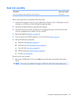
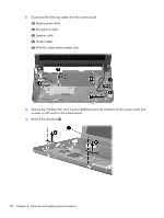
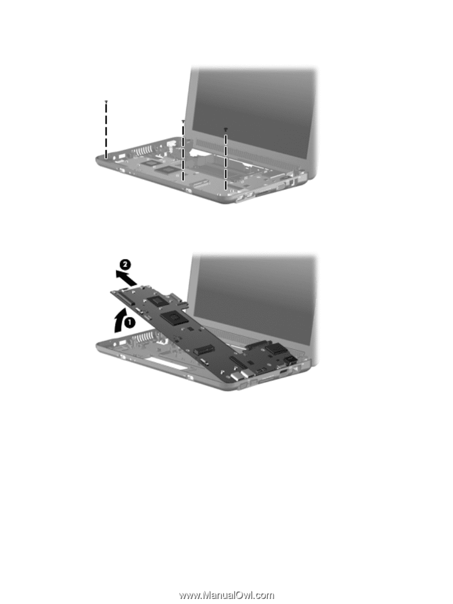
5. Remove the 3 Phillips PM2.5×4.0 screws that secure the system board to the base enclosure. 6. Grasp the system board at the midpoint of the left side (1), and lift it up. 7. Pull the system board (2) out to the left at an angle to remove it. 8. Remove the system board. Reverse the procedure to install the system board. Component replacement procedures 61
-
 1
1 -
2
-
3
-
4
-
5
-
6
-
7
-
8
-
9
-
10
-
11
-
12
-
13
-
14
-
15
-
16
-
17
-
18
-
19
-
20
-
21
-
22
-
23
-
24
-
25
-
26
-
27
-
28
-
29
-
30
-
31
-
32
-
33
-
34
-
35
-
36
-
37
-
38
-
39
-
40
-
41
-
42
-
43
-
44
-
45
-
46
-
47
-
48
-
49
-
50
-
51
-
52
-
53
-
54
-
55
-
56
-
57
-
58
-
59
-
60
-
61
-
62
-
63
-
 64
64 -
 65
65 -
 66
66 -
 67
67 -
 68
68 -
 69
69 -
 70
70 -
 71
71 -
 72
72 -
 73
73 -
 74
74 -
75
-
76
-
77
-
78
-
79
-
80
-
81
-
82
-
83
-
84
-
85
-
86
-
87
-
88
-
89
-
90
-
91
-
92
-
93
-
94
-
95
-
96
-
97
-
98
-
99
-
100
-
101
-
102
-
103
-
104
-
105
-
106
-
107
 |
 |
5.
Remove the 3 Phillips PM2.5×4.0 screws that secure the system board to the base enclosure.
6.
Grasp the system board at the midpoint of the left side
(1)
, and lift it up.
7.
Pull the system board
(2)
out to the left at an angle to remove it.
8.
Remove the system board.
Reverse the procedure to install the system board.
Component replacement procedures
61