HP Pavilion g4-2000 HP Pavilion g4 Notebook PC - Maintenance and Service Guide - Page 101
Display Panel Cable Kit, spare part, Blu-ray Disc BD ROM and DVD
 |
View all HP Pavilion g4-2000 manuals
Add to My Manuals
Save this manual to your list of manuals |
Page 101 highlights
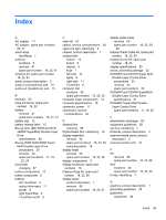
Index A AC adapter 11 AC adapter, spare part numbers 20, 21 action keys identifying 7 antenna locations 5 removal 61 spare part number 18, 22, 61 Antenna Kit, spare part number 18, 22, 61 audio, product description 2 audio-in (microphone) jack 10 audio-out (headphone) jack 10 B backups 83 base enclosure, spare part number 16, 22 battery removal 31 spare part numbers 16, 21, 31 battery bay 12 battery release latch 12 Blu-ray Disc (BD) ROM and DVD ±R/RW SuperMulti Double-Layer Drive specifications 82 Blu-ray ROM DVD±R/RW Super Multi Double-Layer Drive precautions 25 removal 33 spare part numbers 17, 19, 23, 33 boot order changing 87 bottom components 12 button component 6 buttons left TouchPad 9 optical drive eject 11 power 6 right TouchPad 9 TouchPad on/off 9 C cable kit 61 cables, service considerations 24 caps lock light, identifying 8 chipset, product description 1 components bottom 12 button 6 display 5 keys 7 left side 10 lights 8 right side 11 TouchPad 9 computer feet locations 30 spare part number 16, 23, 30 computer major components 14 computer specifications 79 connector, power 11 connectors, service considerations 24 D deleted files restoring 86 Digital Media Slot, identifying 10 display assembly removal 54 spare part numbers 15, 23, 54 subcomponents 18 display bezel removal 56 spare part number 18, 22, 56 display components 5 display enclosure, spare part numbers 18 Display Hinge Kit, spare part number 18, 22, 60 display panel product description 1 removal 58 spare part number 18, 23, 61 display panel cable removal 60 spare part number 18, 22, 59, 60 Display Panel Cable Kit, spare part number 18, 22, 60 Display Screw Kit, spare part number 18, 23 display specifications 80 drives, preventing damage 25 DVD±RW and CD-RW Super Multi Double-Layer Combo Drive precautions 25 removal 33 spare part numbers 33 DVD±RW and CD-RW SuperMulti Double-Layer Combo Drive specifications 81 DVD±RW Super Multi DoubleLayer Combo Drive spare part numbers 17, 19, 22 E electrostatic discharge 25 equipment guidelines 28 esc key, identifying 7 Ethernet, product description 2 external media cards, product description 3 external monitor port 10 F fan removal 68 spare part number feet locations 30 spare part number fn key, identifying 7 16, 22, 68 16, 23, 30 G graphics, product description 1 grounding guidelines 25 guidelines equipment 28 Index 93
-
 1
1 -
2
-
3
-
4
-
5
-
6
-
7
-
8
-
9
-
10
-
11
-
12
-
13
-
14
-
15
-
16
-
17
-
18
-
19
-
20
-
21
-
22
-
23
-
24
-
25
-
26
-
27
-
28
-
29
-
30
-
31
-
32
-
33
-
34
-
35
-
36
-
37
-
38
-
39
-
40
-
41
-
42
-
43
-
44
-
45
-
46
-
47
-
48
-
49
-
50
-
51
-
52
-
53
-
54
-
55
-
56
-
57
-
58
-
59
-
60
-
61
-
62
-
63
-
64
-
65
-
66
-
67
-
68
-
69
-
70
-
71
-
72
-
73
-
74
-
75
-
76
-
77
-
78
-
79
-
80
-
81
-
82
-
83
-
84
-
85
-
86
-
87
-
88
-
89
-
90
-
91
-
92
-
93
-
94
-
95
-
 96
96 -
 97
97 -
 98
98 -
 99
99 -
 100
100 -
 101
101 -
 102
102 -
 103
103 -
 104
104
 |
 |