HP Pavilion g4-2000 HP Pavilion g4 Notebook PC - Maintenance and Service Guide - Page 81
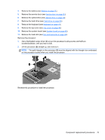
straight up, and remove it., Lift the processor
 |
View all HP Pavilion g4-2000 manuals
Add to My Manuals
Save this manual to your list of manuals |
Page 81 highlights
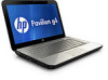
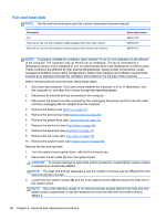
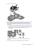
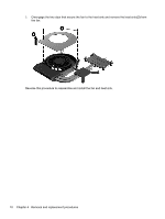
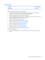
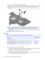
4. Remove the battery (see Battery on page 31). 5. Remove the service door (see Service door on page 32). 6. Remove the optical drive (see Optical drive on page 33). 7. Remove the hard drive (see Hard drive on page 36). 8. Remove the keyboard (see Keyboard on page 43). 9. Remove the top cover (see Top cover on page 46). 10. Remove the system board (see System board on page 65). 11. Remove the heat sink (see Fan and heat sink on page 68). Remove the processor: 1. Use a flat-bladed screw driver (1) to turn the processor locking screw one-half turn counterclockwise, until you hear a click. 2. Lift the processor (2) straight up, and remove it. NOTE: The gold triangle on the processor (3) must be aligned with the triangle icon embossed on the processor socket when you install the processor. Reverse this procedure to install the processor. Component replacement procedures 73
-
 1
1 -
2
-
3
-
4
-
5
-
6
-
7
-
8
-
9
-
10
-
11
-
12
-
13
-
14
-
15
-
16
-
17
-
18
-
19
-
20
-
21
-
22
-
23
-
24
-
25
-
26
-
27
-
28
-
29
-
30
-
31
-
32
-
33
-
34
-
35
-
36
-
37
-
38
-
39
-
40
-
41
-
42
-
43
-
44
-
45
-
46
-
47
-
48
-
49
-
50
-
51
-
52
-
53
-
54
-
55
-
56
-
57
-
58
-
59
-
60
-
61
-
62
-
63
-
64
-
65
-
66
-
67
-
68
-
69
-
70
-
71
-
72
-
73
-
74
-
75
-
 76
76 -
 77
77 -
 78
78 -
 79
79 -
 80
80 -
 81
81 -
 82
82 -
 83
83 -
 84
84 -
 85
85 -
 86
86 -
87
-
88
-
89
-
90
-
91
-
92
-
93
-
94
-
95
-
96
-
97
-
98
-
99
-
100
-
101
-
102
-
103
-
104
 |
 |
