HP Pavilion g4-2000 HP Pavilion g4 Notebook PC - Maintenance and Service Guide - Page 69
Optical drive cable, and then unplugging the AC adapter from the computer.
 |
View all HP Pavilion g4-2000 manuals
Add to My Manuals
Save this manual to your list of manuals |
Page 69 highlights
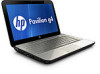
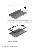
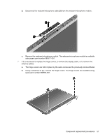
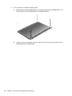
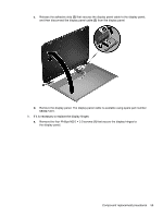
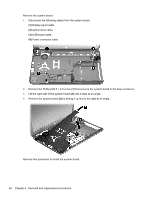
11. If it is necessary to replace the wireless antenna cables and transceivers: a. Release the wireless antenna cables from the clips (1) built into the display enclosure. b. Release the wireless antenna transceivers (2) from the display enclosure. (The wireless antenna transceivers are attached to the display enclosure with double-sided tape.) c. Remove the wireless antenna cables and transceivers. The wireless antenna cables and transceivers are available in the Antenna Kit, spare part number 680539-001. The display panel is available using spare part number 680562-001. Reverse this procedure to reassemble and install the display assembly. Optical drive cable NOTE: The optical drive cable is included in the Cable Kit, spare part number 680546-001. The optical drive cable includes the optical drive connector. Before removing the optical drive cable, follow these steps: 1. Shut down the computer. If you are unsure whether the computer is off or in Hibernation, turn the computer on, and then shut it down through the operating system. 2. Disconnect all external devices connected to the computer. 3. Disconnect the power from the computer by first unplugging the power cord from the AC outlet and then unplugging the AC adapter from the computer. 4. Remove the battery (see Battery on page 31. 5. Remove the service door (see Service door on page 32). 6. Remove the optical drive (see Optical drive on page 33). 7. Remove the hard drive (see Hard drive on page 36). 8. Remove the keyboard (see Keyboard on page 43). 9. Remove the top cover (see Top cover on page 46). Component replacement procedures 61
-
 1
1 -
2
-
3
-
4
-
5
-
6
-
7
-
8
-
9
-
10
-
11
-
12
-
13
-
14
-
15
-
16
-
17
-
18
-
19
-
20
-
21
-
22
-
23
-
24
-
25
-
26
-
27
-
28
-
29
-
30
-
31
-
32
-
33
-
34
-
35
-
36
-
37
-
38
-
39
-
40
-
41
-
42
-
43
-
44
-
45
-
46
-
47
-
48
-
49
-
50
-
51
-
52
-
53
-
54
-
55
-
56
-
57
-
58
-
59
-
60
-
61
-
62
-
63
-
 64
64 -
 65
65 -
 66
66 -
 67
67 -
 68
68 -
 69
69 -
 70
70 -
 71
71 -
 72
72 -
 73
73 -
 74
74 -
75
-
76
-
77
-
78
-
79
-
80
-
81
-
82
-
83
-
84
-
85
-
86
-
87
-
88
-
89
-
90
-
91
-
92
-
93
-
94
-
95
-
96
-
97
-
98
-
99
-
100
-
101
-
102
-
103
-
104
 |
 |
