HP Pavilion g4-2000 HP Pavilion g4 Notebook PC - Maintenance and Service Guide - Page 73
System board, the defective system board and installed on the replacement system board
 |
View all HP Pavilion g4-2000 manuals
Add to My Manuals
Save this manual to your list of manuals |
Page 73 highlights
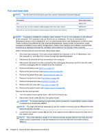
System board NOTE: The system board thermal pad kit, part number 680571-001, includes replacement thermal material. Description For use only with computer models equipped with UMA video memory For use only with computer models equipped with 2048 MB of dedicated discrete video memory For use only with computer models equipped with 1024 MB of dedicated discrete video memory Spare part number 680568-001 680570-001 680569-001 Before removing the system board, follow these steps: 1. Shut down the computer. If you are unsure whether the computer is off or in Hibernation, turn the computer on, and then shut it down through the operating system. 2. Disconnect all external devices connected to the computer. 3. Disconnect the power from the computer by first unplugging the power cord from the AC outlet and then unplugging the AC adapter from the computer. 4. Remove the battery (see Battery on page 31). 5. Remove the service door (see Service door on page 32). 6. Remove the optical drive (see Optical drive on page 33). 7. Remove the hard drive (see Hard drive on page 36). 8. Remove the keyboard (see Keyboard on page 43). 9. Remove the top cover (see Top cover on page 46). When replacing the system board, be sure that the following components are removed from the defective system board and installed on the replacement system board: ● Memory module (see Memory module on page 38) ● RTC battery (see RTC battery on page 67) ● Fan and heat sink (see Fan and heat sink on page 68). ● PCH heat sink (see PCH heat sink on page 71) ● Processor (see Processor on page 72) Component replacement procedures 65
-
 1
1 -
2
-
3
-
4
-
5
-
6
-
7
-
8
-
9
-
10
-
11
-
12
-
13
-
14
-
15
-
16
-
17
-
18
-
19
-
20
-
21
-
22
-
23
-
24
-
25
-
26
-
27
-
28
-
29
-
30
-
31
-
32
-
33
-
34
-
35
-
36
-
37
-
38
-
39
-
40
-
41
-
42
-
43
-
44
-
45
-
46
-
47
-
48
-
49
-
50
-
51
-
52
-
53
-
54
-
55
-
56
-
57
-
58
-
59
-
60
-
61
-
62
-
63
-
64
-
65
-
66
-
67
-
 68
68 -
 69
69 -
 70
70 -
 71
71 -
 72
72 -
 73
73 -
 74
74 -
 75
75 -
 76
76 -
 77
77 -
 78
78 -
79
-
80
-
81
-
82
-
83
-
84
-
85
-
86
-
87
-
88
-
89
-
90
-
91
-
92
-
93
-
94
-
95
-
96
-
97
-
98
-
99
-
100
-
101
-
102
-
103
-
104
 |
 |