HP Pavilion g4-2000 HP Pavilion g4 Notebook PC - Maintenance and Service Guide - Page 76
Fan and heat sink, from the system board.
 |
View all HP Pavilion g4-2000 manuals
Add to My Manuals
Save this manual to your list of manuals |
Page 76 highlights
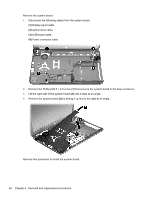
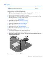
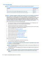
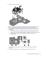
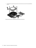
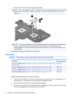
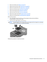
Fan and heat sink NOTE: The fan and heat sink spare part kits include replacement thermal material. Description Fan Heat sink for use only with computer models equipped with UMA video memory Heat sink for use only with computer models equipped with discrete video memory Spare part number 680551-001 680549-001 680550-001 NOTE: To properly ventilate the computer, allow at least 7.6 cm (3 in) of clearance on the left side of the computer. The computer uses an electric fan for ventilation. The fan is controlled by a temperature sensor and is designed to turn on automatically when high temperature conditions exist. These conditions are affected by high external temperatures, system power consumption, power management/battery conservation configurations, battery fast charging, and software requirements. Exhaust air is displaced through the ventilation grill located on the left side of the computer. Before removing the fan and heat sink, follow these steps: 1. Shut down the computer. If you are unsure whether the computer is off or in Hibernation, turn the computer on, and then shut it down through the operating system. 2. Disconnect all external devices connected to the computer. 3. Disconnect the power from the computer by first unplugging the power cord from the AC outlet and then unplugging the AC adapter from the computer. 4. Remove the battery (see Battery on page 31). 5. Remove the service door (see Service door on page 32). 6. Remove the optical drive (see Optical drive on page 33). 7. Remove the hard drive (see Hard drive on page 36). 8. Remove the keyboard (see Keyboard on page 43). 9. Remove the top cover (see Top cover on page 46). 10. Remove the system board (see System board on page 65). Remove the fan and heat sink: 1. Turn the system board upside down, with the front toward you. 2. Disconnect the fan cable (1) from the system board. CAUTION: To prevent damage to heat sinks and/or processors, loosen/tighten captive screws in sequence as numerically labeled. NOTE: The heat sink and fan appearance and the number of screws may be different from the heat sink and fan pictured. 3. Loosen the four captive screws (2) and the three captive screws (3) that secure the heat sink to the system board. NOTE: Due to the adhesive quality of the thermal material located between the heat sink and system board components, it may be necessary to move the heat sink from side to side to detach it. 68 Chapter 4 Removal and replacement procedures
-
 1
1 -
2
-
3
-
4
-
5
-
6
-
7
-
8
-
9
-
10
-
11
-
12
-
13
-
14
-
15
-
16
-
17
-
18
-
19
-
20
-
21
-
22
-
23
-
24
-
25
-
26
-
27
-
28
-
29
-
30
-
31
-
32
-
33
-
34
-
35
-
36
-
37
-
38
-
39
-
40
-
41
-
42
-
43
-
44
-
45
-
46
-
47
-
48
-
49
-
50
-
51
-
52
-
53
-
54
-
55
-
56
-
57
-
58
-
59
-
60
-
61
-
62
-
63
-
64
-
65
-
66
-
67
-
68
-
69
-
70
-
 71
71 -
 72
72 -
 73
73 -
 74
74 -
 75
75 -
 76
76 -
 77
77 -
 78
78 -
 79
79 -
 80
80 -
 81
81 -
82
-
83
-
84
-
85
-
86
-
87
-
88
-
89
-
90
-
91
-
92
-
93
-
94
-
95
-
96
-
97
-
98
-
99
-
100
-
101
-
102
-
103
-
104
 |
 |