HP StorageWorks 2/16V HP StorageWorks SAN Switch 2/8V, 2/16V and 2/16N Instal - Page 51
Set the IP Address, After POST is complete, verify that the System Status and Power Status LEDs
 |
View all HP StorageWorks 2/16V manuals
Add to My Manuals
Save this manual to your list of manuals |
Page 51 highlights
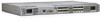
Installing the SAN Switch To protect against AC failure, connect the power cords to outlets on separate circuits. Ensure that the cords have a minimum service loop of six inches available at the connection to the switch and are routed to avoid stress. The power supply LED lights up green, and the switch begins running Power On Post Test (POST). POST should complete and the switch will complete the boot process in about three minutes. 2. After POST is complete, verify that the System Status and Power Status LEDs are green. 3. Using a serial connection, when the terminal emulator application stops reporting information, press Enter to display the login prompt. 4. Log in using the administrative account; the logon is "admin" and the default password is "password". Up to two simultaneous admin sessions and four user sessions can be created. For details, refer to the HP StorageWorks Fabric OS Procedures 4.2x User Guide and the Fabric OS 4.2.x Command Reference Guide. Set the IP Address Replace the default IP address and related information with the information provided by your network administrator:. By default, the IP address is set to 10.77.77.77. 1. Type ipaddrset at the terminal emulator application prompt. 2. Type the requested information as prompted. Example: switch:admin> ipaddrset Ethernet IP Address [192.168.1.1]:10.32.53.47 Ethernet Subnetmask [255.255.255.0]:255.255.240.0 Fibre Channel IP Address [0.0.0.0]: Fibre Channel Subnetmask [0.0.0.0]: Gateway IP Address [0.0.0.0]:10.32.48.1 Set IP address now? [y = set now, n = next reboot]:y IP address being changed... Committing configuration...Done. switch:admin> 3. Optionally, verify that the address was correctly set by entering the ipaddrshow command at the prompt. 4. Record the IP address on the label clearly displayed on the port side of the chassis. SAN Switch 2/8V, 2/16V and 2/16N Installation Guide 51
-
 1
1 -
2
-
3
-
4
-
5
-
6
-
7
-
8
-
9
-
10
-
11
-
12
-
13
-
14
-
15
-
16
-
17
-
18
-
19
-
20
-
21
-
22
-
23
-
24
-
25
-
26
-
27
-
28
-
29
-
30
-
31
-
32
-
33
-
34
-
35
-
36
-
37
-
38
-
39
-
40
-
41
-
42
-
43
-
44
-
45
-
 46
46 -
 47
47 -
 48
48 -
 49
49 -
 50
50 -
 51
51 -
 52
52 -
 53
53 -
 54
54 -
 55
55 -
 56
56 -
57
-
58
-
59
-
60
-
61
-
62
-
63
-
64
-
65
-
66
-
67
-
68
-
69
-
70
-
71
-
72
-
73
-
74
-
75
-
76
-
77
-
78
-
79
-
80
-
81
-
82
-
83
-
84
-
85
-
86
-
87
-
88
-
89
-
90
-
91
-
92
-
93
-
94
-
95
-
96
-
97
-
98
-
99
-
100
-
101
-
102
-
103
-
104
-
105
-
106
-
107
-
108
-
109
-
110
-
111
-
112
-
113
-
114
-
115
-
116
 |
 |
