HP Surestore 28/48-Slot with DLT7000 HP SureStore Fibre Channel SCSI Bridge 21 - Page 27
Mounting the Fibre Bridge in a Rack
 |
View all HP Surestore 28/48-Slot with DLT7000 manuals
Add to My Manuals
Save this manual to your list of manuals |
Page 27 highlights
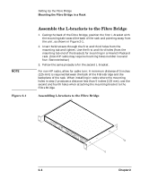
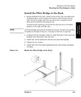
Setting Up the Fibre Bridge NOTE Table 2-1 Setting Up the Fibre Bridge Mounting the Fibre Bridge in a Rack Mounting the Fibre Bridge in a Rack Mounting the Fibre Bridge in a rack requires assembling L-brackets to the Fibre Bridge and then mounting the L-brackets to a rack. L-brackets allow the Fibre Bridge to be mounted in a fixed position, near the back of a rack. All connections and user displays are located on the back of the Fibre Bridge. Consequently, mount toward the back of a rack. Before you begin, verify you have the assembly components listed in Table 2-1. Assembly Components Tool Mounting brackets Rackmount screws and nuts Filler panel decal 1 1 pair 1 package (Includes extra parts) 1 #2 Phillips screwdriver (not supplied). L-brackets, for assembly with Fibre Bridge. Six (6) 6x32 screws to attach Fibre Bridge to L-brackets. Six (6) 10x32 screws and six (6) clip nuts for installing the Fibre Bridge (with L-brackets attached) into a rack. Decal for filler panel, provided by customer (supplied separately by rack manufacturer). Chapter 2 2- 3
-
 1
1 -
2
-
3
-
4
-
5
-
6
-
7
-
8
-
9
-
10
-
11
-
12
-
13
-
14
-
15
-
16
-
17
-
18
-
19
-
20
-
21
-
 22
22 -
 23
23 -
 24
24 -
 25
25 -
 26
26 -
 27
27 -
 28
28 -
 29
29 -
 30
30 -
 31
31 -
 32
32 -
33
-
34
-
35
-
36
-
37
-
38
-
39
-
40
-
41
-
42
-
43
-
44
-
45
-
46
-
47
-
48
-
49
-
50
-
51
-
52
-
53
-
54
-
55
-
56
-
57
-
58
-
59
-
60
-
61
-
62
-
63
-
64
-
65
-
66
-
67
-
68
-
69
-
70
-
71
-
72
-
73
-
74
-
75
-
76
-
77
-
78
-
79
-
80
-
81
-
82
-
83
-
84
-
85
-
86
-
87
-
88
-
89
-
90
-
91
-
92
-
93
-
94
-
95
 |
 |
