HP Surestore 28/48-Slot with DLT7000 HP SureStore Fibre Channel SCSI Bridge 21 - Page 29
Install the Fibre Bridge in the Rack
 |
View all HP Surestore 28/48-Slot with DLT7000 manuals
Add to My Manuals
Save this manual to your list of manuals |
Page 29 highlights
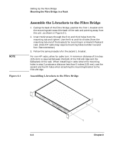
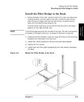
Setting Up the Fibre Bridge NOTE Figure 2-2 Setting Up the Fibre Bridge Mounting the Fibre Bridge in a Rack Install the Fibre Bridge in the Rack 1. Facing the back of the rack, install a total of four clip nuts above any existing product, two into each of the rails. Install the clip nuts so that the top nut aligns with the top hole of the L-bracket and the other with the bottom hole. (Figure 2-2). To ensure level mounting, verify that the clip nuts are in the same position on the right and left rails. The Fibre Bridge mounts from the back of the rack. All user functionality is located on the back of the unit; no access to the front is required. 2. Holding the Fibre Bridge in position, align the holes in the mounting brackets with the holes in the clip nuts. 3. Install four 10x32 screws into the clip nuts and hand-tighten. 4. Tighten all four screws. 5. Install the front filler panel (supplied by the rack vendor) and apply the decal. Mount the Fibre Bridge in the Rack H Not Suitable for Hard Drive Subsystems Chapter 2 2- 5
-
 1
1 -
2
-
3
-
4
-
5
-
6
-
7
-
8
-
9
-
10
-
11
-
12
-
13
-
14
-
15
-
16
-
17
-
18
-
19
-
20
-
21
-
22
-
23
-
 24
24 -
 25
25 -
 26
26 -
 27
27 -
 28
28 -
 29
29 -
 30
30 -
 31
31 -
 32
32 -
 33
33 -
 34
34 -
35
-
36
-
37
-
38
-
39
-
40
-
41
-
42
-
43
-
44
-
45
-
46
-
47
-
48
-
49
-
50
-
51
-
52
-
53
-
54
-
55
-
56
-
57
-
58
-
59
-
60
-
61
-
62
-
63
-
64
-
65
-
66
-
67
-
68
-
69
-
70
-
71
-
72
-
73
-
74
-
75
-
76
-
77
-
78
-
79
-
80
-
81
-
82
-
83
-
84
-
85
-
86
-
87
-
88
-
89
-
90
-
91
-
92
-
93
-
94
-
95
 |
 |