HP Surestore 28/48-Slot with DLT7000 HP SureStore Fibre Channel SCSI Bridge 21 - Page 28
Assemble the L-brackets to the Fibre Bridge
 |
View all HP Surestore 28/48-Slot with DLT7000 manuals
Add to My Manuals
Save this manual to your list of manuals |
Page 28 highlights
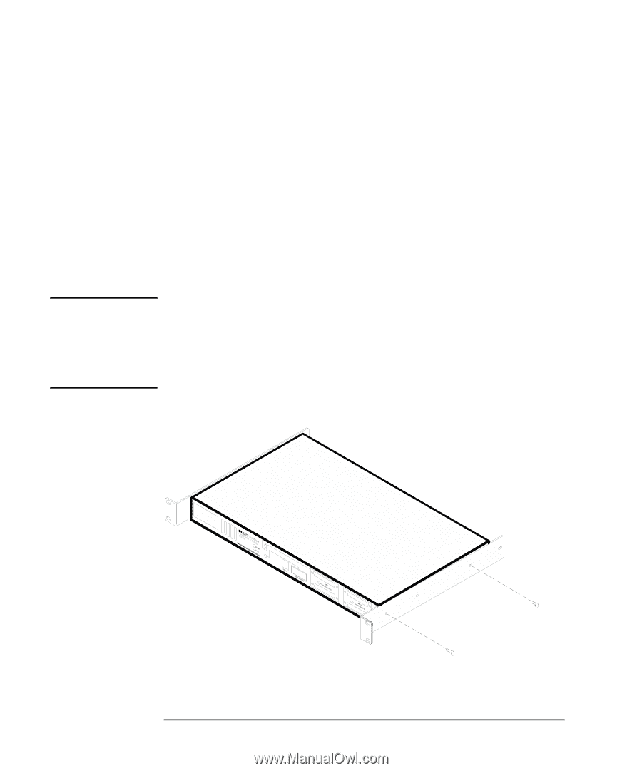
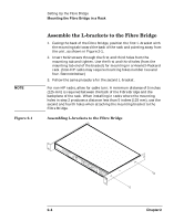
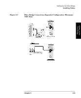
NOTE Figure 2-1 Setting Up the Fibre Bridge Mounting the Fibre Bridge in a Rack Assemble the L-brackets to the Fibre Bridge 1. Facing the back of the Fibre Bridge, position the first L-bracket with the mounting tab toward the back of the rack and pointing away from the unit, as shown in Figure 2-1. 2. Insert 6x32 screws through the first and third holes from the mounting tab and tighten. Use the first and third holes (from the mounting tab end of the bracket) for mounting in a Hewlett-Packard rack. (Non-HP racks may require mounting holes number two and four. See note below.) 3. Follow the same procedure for the second L-bracket. For non-HP racks, allow for cable turn: A minimum distance of 5 inches (125 mm) is required between the back of the Fibre Bridge and the backplane of the rack. When installing in racks where the mounting holes in step 2 produces a distance less than 5 inches (125 mm), use the second and fourth holes when attaching the mounting bracket to the Fibre Bridge. Assembling L-brackets to the Fibre Bridge H Not Suitable for Hard Drive Subsystems 2- 4 Chapter 2
-
 1
1 -
2
-
3
-
4
-
5
-
6
-
7
-
8
-
9
-
10
-
11
-
12
-
13
-
14
-
15
-
16
-
17
-
18
-
19
-
20
-
21
-
22
-
 23
23 -
 24
24 -
 25
25 -
 26
26 -
 27
27 -
 28
28 -
 29
29 -
 30
30 -
 31
31 -
 32
32 -
 33
33 -
34
-
35
-
36
-
37
-
38
-
39
-
40
-
41
-
42
-
43
-
44
-
45
-
46
-
47
-
48
-
49
-
50
-
51
-
52
-
53
-
54
-
55
-
56
-
57
-
58
-
59
-
60
-
61
-
62
-
63
-
64
-
65
-
66
-
67
-
68
-
69
-
70
-
71
-
72
-
73
-
74
-
75
-
76
-
77
-
78
-
79
-
80
-
81
-
82
-
83
-
84
-
85
-
86
-
87
-
88
-
89
-
90
-
91
-
92
-
93
-
94
-
95
 |
 |