HP Tc4200 HP Compaq tc4200 Tablet PC - Maintenance and Service Guide - Page 28
Design Overview - parts
 |
View all HP Tc4200 manuals
Add to My Manuals
Save this manual to your list of manuals |
Page 28 highlights
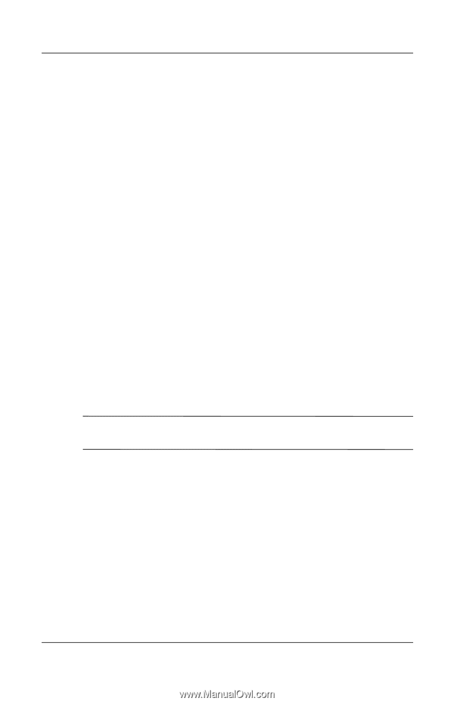
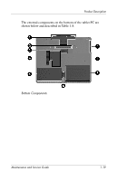
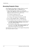
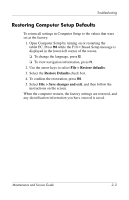
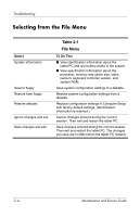
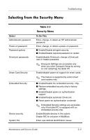
Product Description 1.5 Design Overview This section presents a design overview of key parts and features of the tablet PC. Refer to Chapter 4, "Illustrated Parts Catalog," to identify replacement parts, and Chapter 6, "Removal and Replacement Procedures," for disassembly steps. The system board provides the following device connections: ■ Audio ■ Display ■ Hard drive ■ Intel Pentium M and Celeron M processors ■ Keyboard ■ Memory module ■ Mini PCI communications devices ■ PC Card ■ Pointing stick ■ TouchPad ■ Trusted platform module (TPM) security module Ä CAUTION: To properly ventilate the tablet PC, allow at least a 7.6-cm (3-inch) clearance on the left and right sides of the tablet PC. The tablet PC uses an electric fan for ventilation. The fan is controlled by a temperature sensor and is designed to be turned on automatically when high temperature conditions exist. These conditions are affected by high external temperatures, system power consumption, power management/battery conservation configurations, battery fast charging, and software applications. Exhaust air is displaced through the ventilation grill located on the left side of the tablet PC. Maintenance and Service Guide 1-21
-
 1
1 -
2
-
3
-
4
-
5
-
6
-
7
-
8
-
9
-
10
-
11
-
12
-
13
-
14
-
15
-
16
-
17
-
18
-
19
-
20
-
21
-
22
-
 23
23 -
 24
24 -
 25
25 -
 26
26 -
 27
27 -
 28
28 -
 29
29 -
 30
30 -
 31
31 -
 32
32 -
 33
33 -
34
-
35
-
36
-
37
-
38
-
39
-
40
-
41
-
42
-
43
-
44
-
45
-
46
-
47
-
48
-
49
-
50
-
51
-
52
-
53
-
54
-
55
-
56
-
57
-
58
-
59
-
60
-
61
-
62
-
63
-
64
-
65
-
66
-
67
-
68
-
69
-
70
-
71
-
72
-
73
-
74
-
75
-
76
-
77
-
78
-
79
-
80
-
81
-
82
-
83
-
84
-
85
-
86
-
87
-
88
-
89
-
90
-
91
-
92
-
93
-
94
-
95
-
96
-
97
-
98
-
99
-
100
-
101
-
102
-
103
-
104
-
105
-
106
-
107
-
108
-
109
-
110
-
111
-
112
-
113
-
114
-
115
-
116
-
117
-
118
-
119
-
120
-
121
-
122
-
123
-
124
-
125
-
126
-
127
-
128
-
129
-
130
-
131
-
132
-
133
-
134
-
135
-
136
-
137
-
138
-
139
-
140
-
141
-
142
-
143
-
144
-
145
-
146
-
147
-
148
-
149
-
150
-
151
-
152
-
153
-
154
-
155
-
156
-
157
-
158
-
159
-
160
-
161
-
162
-
163
-
164
-
165
-
166
-
167
-
168
-
169
-
170
-
171
-
172
-
173
-
174
-
175
-
176
-
177
-
178
-
179
-
180
-
181
-
182
-
183
-
184
-
185
-
186
-
187
-
188
-
189
-
190
-
191
-
192
-
193
-
194
-
195
-
196
-
197
-
198
-
199
 |
 |