HP Tc4200 HP Compaq tc4200 Tablet PC - Maintenance and Service Guide - Page 93
Disassembly Sequence Chart, Description - keyboard removal
 |
View all HP Tc4200 manuals
Add to My Manuals
Save this manual to your list of manuals |
Page 93 highlights
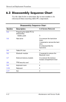
Removal and Replacement Procedures 6.2 Disassembly Sequence Chart Use the chart below to determine the section number to be referenced when removing tablet PC components. Section 6.3 6.4 6.5 6.6 6.7 6.8 6.9 6.10 6.11 Disassembly Sequence Chart Description Preparing the tablet PC for disassembly Battery pack Hard drive Tablet PC feet Bluetooth module External memory module TPM security card Keyboard cover Keyboard Fan # of Screws Removed 0 2 to remove the hard drive cover 1 loosened to remove the hard drive 4 to disassemble the hard drive 0 2 loosened to remove the Bluetooth cover 2 to remove the memory module compartment cover 1 4 4 3 6-2 Maintenance and Service Guide
-
 1
1 -
2
-
3
-
4
-
5
-
6
-
7
-
8
-
9
-
10
-
11
-
12
-
13
-
14
-
15
-
16
-
17
-
18
-
19
-
20
-
21
-
22
-
23
-
24
-
25
-
26
-
27
-
28
-
29
-
30
-
31
-
32
-
33
-
34
-
35
-
36
-
37
-
38
-
39
-
40
-
41
-
42
-
43
-
44
-
45
-
46
-
47
-
48
-
49
-
50
-
51
-
52
-
53
-
54
-
55
-
56
-
57
-
58
-
59
-
60
-
61
-
62
-
63
-
64
-
65
-
66
-
67
-
68
-
69
-
70
-
71
-
72
-
73
-
74
-
75
-
76
-
77
-
78
-
79
-
80
-
81
-
82
-
83
-
84
-
85
-
86
-
87
-
 88
88 -
 89
89 -
 90
90 -
 91
91 -
 92
92 -
 93
93 -
 94
94 -
 95
95 -
 96
96 -
 97
97 -
 98
98 -
99
-
100
-
101
-
102
-
103
-
104
-
105
-
106
-
107
-
108
-
109
-
110
-
111
-
112
-
113
-
114
-
115
-
116
-
117
-
118
-
119
-
120
-
121
-
122
-
123
-
124
-
125
-
126
-
127
-
128
-
129
-
130
-
131
-
132
-
133
-
134
-
135
-
136
-
137
-
138
-
139
-
140
-
141
-
142
-
143
-
144
-
145
-
146
-
147
-
148
-
149
-
150
-
151
-
152
-
153
-
154
-
155
-
156
-
157
-
158
-
159
-
160
-
161
-
162
-
163
-
164
-
165
-
166
-
167
-
168
-
169
-
170
-
171
-
172
-
173
-
174
-
175
-
176
-
177
-
178
-
179
-
180
-
181
-
182
-
183
-
184
-
185
-
186
-
187
-
188
-
189
-
190
-
191
-
192
-
193
-
194
-
195
-
196
-
197
-
198
-
199
 |
 |

6–2
Maintenance and Service Guide
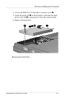
Removal and Replacement Procedures
6.2
Disassembly Sequence Chart
Use the chart below to determine the section number to be
referenced when removing tablet PC components.
Disassembly Sequence Chart
Section
Description
# of Screws Removed
6.3
Preparing the tablet PC for
disassembly
Battery pack
0
6.4
Hard drive
2 to remove the hard drive
cover
1 loosened to remove the hard
drive
4 to disassemble the
hard drive
6.5
Tablet PC feet
0
6.6
Bluetooth module
2 loosened to remove the
Bluetooth cover
6.7
External memory module
2 to remove the memory
module compartment cover
6.8
TPM security card
1
6.9
Keyboard cover
4
6.10
Keyboard
4
6.11
Fan
3