HP TouchSmart tx2-1109au HP TouchSmart tx2 Notebook PC - Maintenance and Servi - Page 62
CAUTION, Open the computer.
 |
View all HP TouchSmart tx2-1109au manuals
Add to My Manuals
Save this manual to your list of manuals |
Page 62 highlights
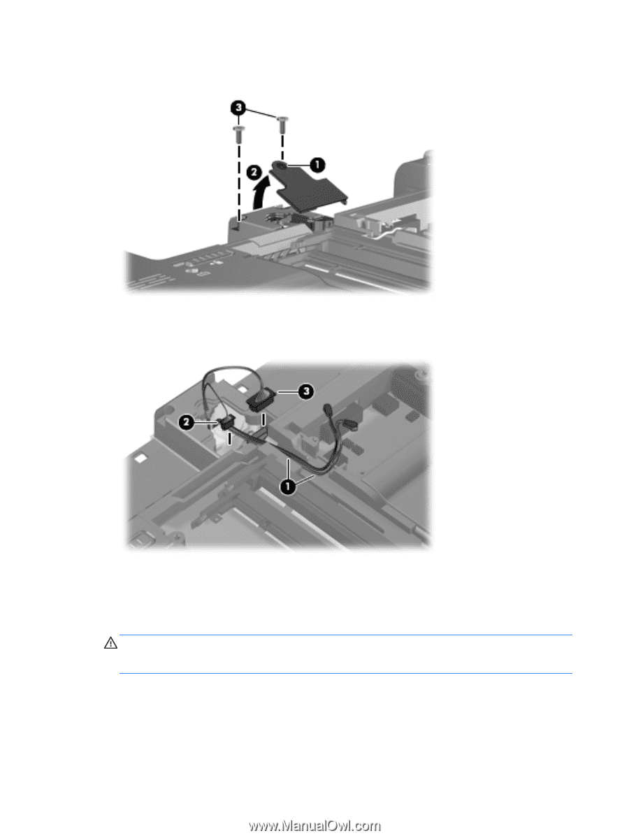
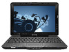
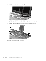
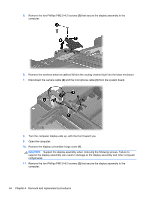
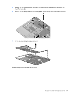
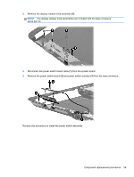
5. Remove the two Phillips PM2.5×6.0 screws (3) that secure the display assembly to the computer. 6. Remove the wireless antenna cables (1) from the routing channel built into the base enclosure. 7. Disconnect the camera cable (2) and the microphone cable (3) from the system board. 8. Turn the computer display-side up, with the front toward you. 9. Open the computer. 10. Remove the display convertible hinge cover (1). CAUTION: Support the display assembly when removing the following screws. Failure to support the display assembly can result in damage to the display assembly and other computer components. 11. Remove the two Phillips PM2.5×6.0 screws (2) that secure the display assembly to the computer. 54 Chapter 4 Removal and replacement procedures
-
 1
1 -
2
-
3
-
4
-
5
-
6
-
7
-
8
-
9
-
10
-
11
-
12
-
13
-
14
-
15
-
16
-
17
-
18
-
19
-
20
-
21
-
22
-
23
-
24
-
25
-
26
-
27
-
28
-
29
-
30
-
31
-
32
-
33
-
34
-
35
-
36
-
37
-
38
-
39
-
40
-
41
-
42
-
43
-
44
-
45
-
46
-
47
-
48
-
49
-
50
-
51
-
52
-
53
-
54
-
55
-
56
-
 57
57 -
 58
58 -
 59
59 -
 60
60 -
 61
61 -
 62
62 -
 63
63 -
 64
64 -
 65
65 -
 66
66 -
 67
67 -
68
-
69
-
70
-
71
-
72
-
73
-
74
-
75
-
76
-
77
-
78
-
79
-
80
-
81
-
82
-
83
-
84
-
85
-
86
-
87
-
88
-
89
-
90
-
91
-
92
-
93
-
94
-
95
-
96
-
97
-
98
-
99
-
100
-
101
-
102
-
103
-
104
-
105
-
106
-
107
-
108
-
109
-
110
-
111
-
112
-
113
-
114
-
115
-
116
-
117
-
118
-
119
-
120
-
121
-
122
-
123
 |
 |