HP TouchSmart tx2-1109au HP TouchSmart tx2 Notebook PC - Maintenance and Servi - Page 71
until the power, is clear of the base enclosure.
 |
View all HP TouchSmart tx2-1109au manuals
Add to My Manuals
Save this manual to your list of manuals |
Page 71 highlights
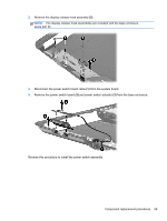
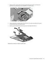
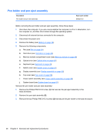
3. Release the ZIF connector (1) to which the audio/infrared board cable is connected and disconnect the audio/infrared board cable (2) from the system board. 4. Use the optical drive connector (1) to lift the left side of the system board (2) until the power connector (3) is clear of the base enclosure. 5. Pull the system board (4) away from the top cover at an angle and remove it. Reverse this procedure to install the system board. Component replacement procedures 63
-
 1
1 -
2
-
3
-
4
-
5
-
6
-
7
-
8
-
9
-
10
-
11
-
12
-
13
-
14
-
15
-
16
-
17
-
18
-
19
-
20
-
21
-
22
-
23
-
24
-
25
-
26
-
27
-
28
-
29
-
30
-
31
-
32
-
33
-
34
-
35
-
36
-
37
-
38
-
39
-
40
-
41
-
42
-
43
-
44
-
45
-
46
-
47
-
48
-
49
-
50
-
51
-
52
-
53
-
54
-
55
-
56
-
57
-
58
-
59
-
60
-
61
-
62
-
63
-
64
-
65
-
 66
66 -
 67
67 -
 68
68 -
 69
69 -
 70
70 -
 71
71 -
 72
72 -
 73
73 -
 74
74 -
 75
75 -
 76
76 -
77
-
78
-
79
-
80
-
81
-
82
-
83
-
84
-
85
-
86
-
87
-
88
-
89
-
90
-
91
-
92
-
93
-
94
-
95
-
96
-
97
-
98
-
99
-
100
-
101
-
102
-
103
-
104
-
105
-
106
-
107
-
108
-
109
-
110
-
111
-
112
-
113
-
114
-
115
-
116
-
117
-
118
-
119
-
120
-
121
-
122
-
123
 |
 |
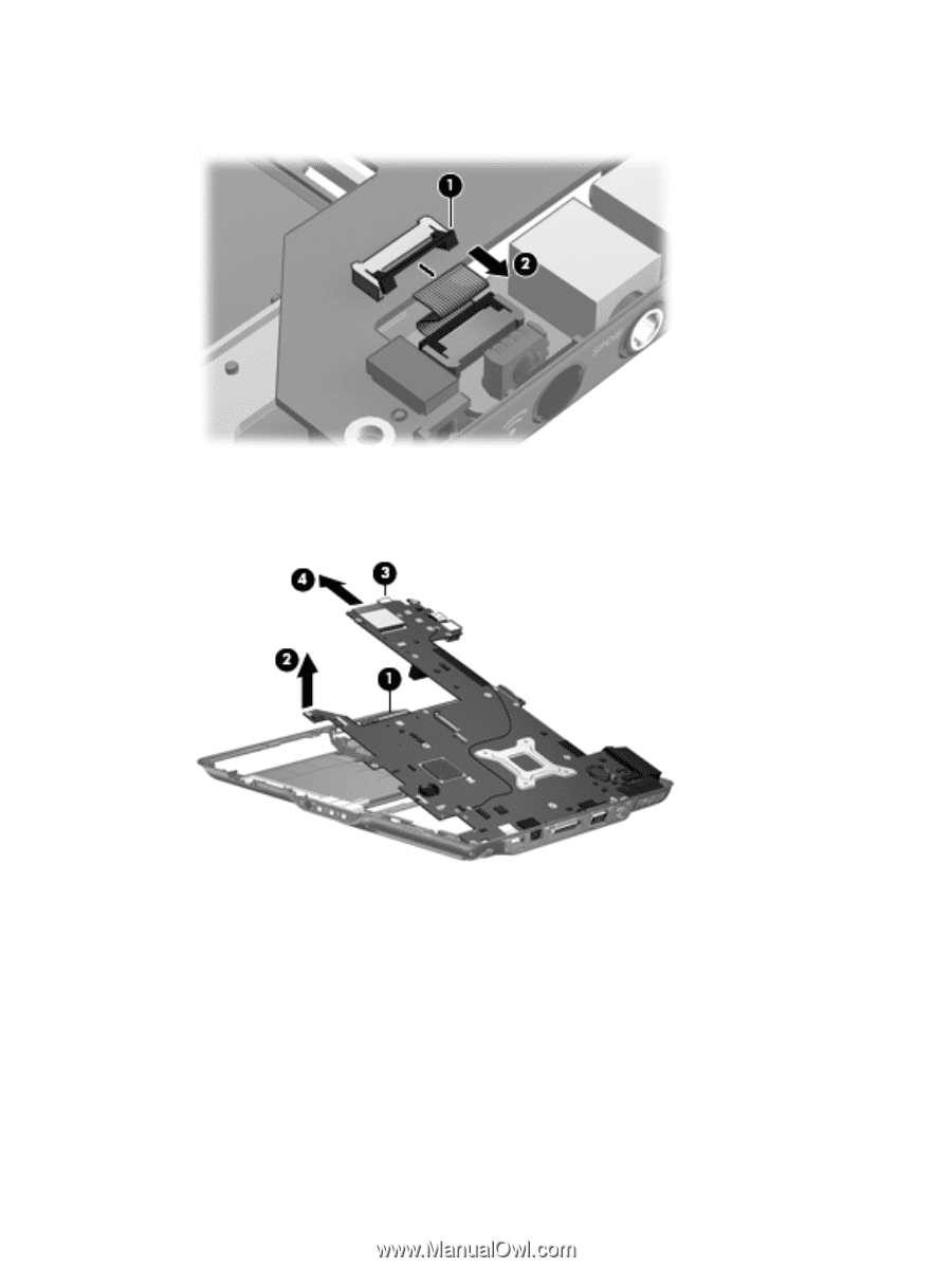
3.
Release the ZIF connector
(1)
to which the audio/infrared board cable is connected and
disconnect the audio/infrared board cable
(2)
from the system board.
4.
Use the optical drive connector
(1)
to lift the left side of the system board
(2)
until the power
connector
(3)
is clear of the base enclosure.
5.
Pull the system board
(4)
away from the top cover at an angle and remove it.
Reverse this procedure to install the system board.
Component replacement procedures
63