HP TouchSmart tx2-1109au HP TouchSmart tx2 Notebook PC - Maintenance and Servi - Page 70
Remove the system board, Power switch assembly see
 |
View all HP TouchSmart tx2-1109au manuals
Add to My Manuals
Save this manual to your list of manuals |
Page 70 highlights
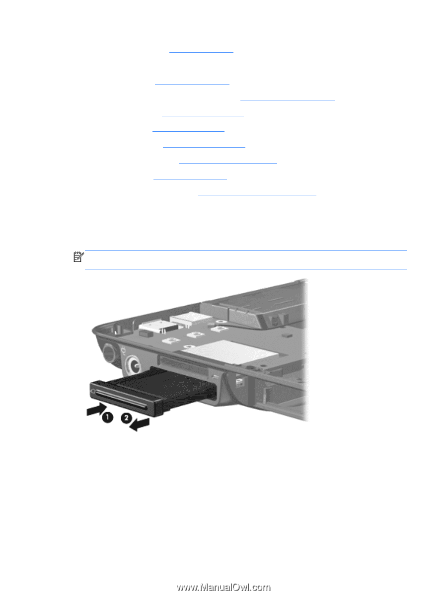
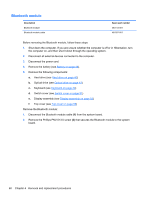
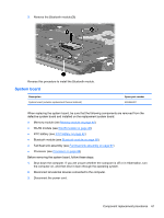
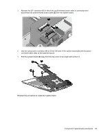
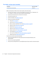
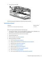
4. Remove the battery (see Battery on page 38). 5. Remove the following components: a. Hard drive (see Hard drive on page 40) b. Memory module compartment cover (see Memory module on page 44) c. Optical drive (see Optical drive on page 43) d. Keyboard (see Keyboard on page 49) e. Switch cover (see Switch cover on page 51) f. Display assembly (see Display assembly on page 53) g. Top cover (see Top cover on page 56) h. Power switch assembly (see Power switch assembly on page 58) Remove the system board: 1. Press in on the ExpressCard slot bezel (1) to release the bezel from the ExpressCard slot. 2. Remove the ExpressCard slot bezel (2) from the ExpressCard slot. NOTE: The ExpressCard slot bezel is included in the Plastics Kit, spare part number 487926-001. 62 Chapter 4 Removal and replacement procedures
-
 1
1 -
2
-
3
-
4
-
5
-
6
-
7
-
8
-
9
-
10
-
11
-
12
-
13
-
14
-
15
-
16
-
17
-
18
-
19
-
20
-
21
-
22
-
23
-
24
-
25
-
26
-
27
-
28
-
29
-
30
-
31
-
32
-
33
-
34
-
35
-
36
-
37
-
38
-
39
-
40
-
41
-
42
-
43
-
44
-
45
-
46
-
47
-
48
-
49
-
50
-
51
-
52
-
53
-
54
-
55
-
56
-
57
-
58
-
59
-
60
-
61
-
62
-
63
-
64
-
 65
65 -
 66
66 -
 67
67 -
 68
68 -
 69
69 -
 70
70 -
 71
71 -
 72
72 -
 73
73 -
 74
74 -
 75
75 -
76
-
77
-
78
-
79
-
80
-
81
-
82
-
83
-
84
-
85
-
86
-
87
-
88
-
89
-
90
-
91
-
92
-
93
-
94
-
95
-
96
-
97
-
98
-
99
-
100
-
101
-
102
-
103
-
104
-
105
-
106
-
107
-
108
-
109
-
110
-
111
-
112
-
113
-
114
-
115
-
116
-
117
-
118
-
119
-
120
-
121
-
122
-
123
 |
 |