Honeywell WAVE2EX Setup Guide - Page 7
Full Line Seizure Connections - ademco
 |
UPC - 781410215504
View all Honeywell WAVE2EX manuals
Add to My Manuals
Save this manual to your list of manuals |
Page 7 highlights
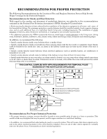
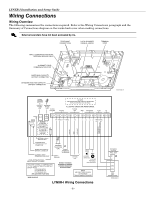
LYNXR-I Installation and Setup Guide Wiring Connections 1. Make Earth Ground Connection - The designated earth ground terminal (1) must be terminated in a good earth ground for the lightning transient protective devices in this product to be effective. The following are examples of good earth grounds available at most installations: Metal Cold Water Pipe - Secure a non-corrosive metal strap (copper is recommended) to the pipe that is electrically connected and secured to which the ground lead is electrically connected and secured. AC Power Outlet Ground - Available from 3-prong, 120VAC power outlets only. To test the integrity of the ground terminal, use a three-wire circuit tester with neon lamp indicators, such as the UL Listed Ideal Model 61-035, or equivalent, available at most electrical supply stores. a. Connect terminal 1 to a good earth ground. 2. Make Phone Line Connections - For local or full line seizure proceed to the appropriate steps below. Local Seizure a. Connect the incoming phone line to either the 8-position jack or terminals 2 (TIP) and 3 (RING) on the Lynx. INCOMING PHONE LINE RING TIP b. Connect the handset phone lines to either the RJ11 jack or terminals 4 (TIP) and 5 (RING). Full Line Seizure: The control must be placed in series with the incoming phone line. Plugging the Direct Connect Cord directly into the RJ31X jack, allows the control to seize the phone line when an alarm occurs and normal phone line usage by the premises phones if the plug needs to be removed. RED GREY 4 5 3 6 RJ31X 2 7 1 8 GREEN TO PREMISES PHONES RING TIP BROWN DIRECT CONNECT CORD c. Cut the incoming RING and TIP phone lines (typically red and green, respectively) and connect them to RJ31X terminals 4 (red) and OR 5 (green). d. Connect the premises end of the cut RING and TIP wires to RJ31X terminals 1 (grey) and 8 (brown) respectively. e. Wire the flying leads of a Direct Connect Cord to the control's phone terminals as shown in the diagram or plug into the 8-position jack. f. Plug the Direct Connect Cord into the RJ31X jack. GREEN RED BROWN GREY TIP RING TIP RING } } INCOMING PHONE LINE TO PREMISES PHONES 8-POSITION JACK Full Line Seizure Connections 01000-008-V0 UL Do not remove the local sounder shorting jumper (shunt). External sounders and powerline carrier devices have not been evaluated by UL LOCAL SOUNDER DISABLE: The Master Keypad's built-in piezo sounder can be disabled by removing the shorting jumper (shunt) on the terminal board. If disabled, however, no sounding will occur upon AC loss, since the external sounder does not operate when AC power is lost. 3. Make External Sounder Connections - The control panel supports either a 6-14VDC piezo sounder (30mA max.) or 6-14VDC bell (120mA max.; e.g. ADEMCO WAVE2EX). a. Connect a piezo sounder to terminals 10 (+) and 11 (-); OR a bell to terminals 11 (-) and 12 (+). 4. Disable Local Sounder Option - If required the Master Keypad's built-in piezo sounder can be disabled. a. Remove the shorting jumper (shunt) on the terminal board. 5. Make Powerline Carrier Device Connections - The control panel supports up to 8 Powerline Carrier Devices. If using these devices, they must be connected to the K10145X10 transformer, as shown in the SUMMARY OF CONNECTIONS diagram. a. Connect the com/data/sync/ lines from the transformer to terminals 9, 13, and 14, respectively. If not using the supplied connection cable, you may need to reverse the black and yellow wire connections. Refer to the ✻80 Device Programming Menu Mode section for details on programming Powerline Carrier Devices. - 7 -
-
 1
1 -
 2
2 -
 3
3 -
 4
4 -
 5
5 -
 6
6 -
 7
7 -
 8
8 -
 9
9 -
 10
10 -
 11
11 -
 12
12 -
13
-
14
-
15
-
16
-
17
-
18
-
19
-
20
-
21
-
22
-
23
-
24
-
25
-
26
-
27
-
28
-
29
-
30
-
31
-
32
-
33
-
34
-
35
-
36
-
37
-
38
-
39
-
40
-
41
-
42
-
43
-
44
-
45
-
46
-
47
-
48
-
49
-
50
-
51
-
52
-
53
-
54
-
55
-
56
-
57
-
58
-
59
-
60
-
61
-
62
-
63
-
64
-
65
-
66
-
67
-
68
-
69
-
70
-
71
-
72
 |
 |
