Icom IC-SAT100M Basic Manual eng/ger/esp/fra/ita - Page 12
CONNECTING AND MAINTENANCE, Rear panel connection
 |
View all Icom IC-SAT100M manuals
Add to My Manuals
Save this manual to your list of manuals |
Page 12 highlights
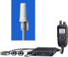
4 CONNECTING AND MAINTENANCE ■ Rear panel connection 1 5 Optional speaker 2 4 R WARNING! NEVER remove the fuse holders from the DC power cable. 3 Red : +, Black : _ NOTE: Use the terminals as shown below for the cable connections. Crimp Solder 4 Fuse holders 12 V or 24 V Battery 1 EXTERNAL SPEAKER JACK Connect a 4 Ω external speaker. 2 IGNITION LEAD Connect to an ignition line. CAUTION: DO NOT put pressure on this lead. Binding to the DC power cable is recommended. 3 DC POWER CONNECTOR Connect to a 12 V/24 V DC battery. Pay attention to polarities. Red line: +, Black line: _ L You can also connect the optional AC adapter. CAUTION: DO NOT reverse the DC power cable polarity when connecting to a power source. This could damage the transceiver. 4 LAN CABLE (Gray: for antenna, Black: for IP Network) Connect the supplied antenna or network devices such as a HUB. L Change the static IP address when the transceiver is connected to network devices. Before using the transceiver, setting a static IP address to the antenna unit and the main unit. Default: Main Unit : 192.168.0.1, Antenna Unit : 192.168.0.2 5 D-Sub 25-pin Connect to use the function extension. Ask your dealer for details. Installing the outdoor antennas Keep a minimum of 20 cm (7.9 inch) between the Antenna unit and your body. 20 cm 7.9 inch Move away from buildings and use the transceiver in areas with an open sky. CAUTION: DO NOT connect other than network devices, such as microphone. This could damage the transceiver. 8° Install the outdoor antennas in a place with a clear view of the sky. Make sure that there are no obstacles, such as buildings or trees, at higher than about 8 degrees around the antenna. 11
-
 1
1 -
2
-
3
-
4
-
5
-
6
-
 7
7 -
 8
8 -
 9
9 -
 10
10 -
 11
11 -
 12
12 -
 13
13 -
 14
14 -
 15
15 -
 16
16 -
 17
17 -
18
-
19
-
20
-
21
-
22
-
23
-
24
-
25
-
26
-
27
-
28
-
29
-
30
-
31
-
32
-
33
-
34
-
35
-
36
-
37
-
38
-
39
-
40
-
41
-
42
-
43
-
44
-
45
-
46
-
47
-
48
-
49
-
50
-
51
-
52
-
53
-
54
-
55
-
56
-
57
-
58
-
59
-
60
-
61
-
62
-
63
-
64
 |
 |
