Invacare TDXSPREE-CG Owners Manual 2 - Page 86
SETUP/MAINTENANCE, Invacare® TDX® SC, Invacare TDX Spree, Part No 1149267
 |
View all Invacare TDXSPREE-CG manuals
Add to My Manuals
Save this manual to your list of manuals |
Page 86 highlights
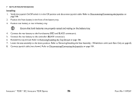
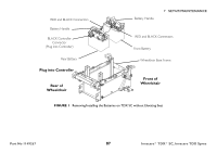
7 SETUP/MAINTENANCE Installing 1. Verify the joystick On/Off switch is in the Off position and disconnect joystick cable. Refer to Disconnecting/Connecting the Joysticks on page 104. 2. Position the front battery in the front of the battery tray. 3. Position rear battery in rear of battery tray. Ensure that both batteries are properly seated and resting on the battery tray. 4. Connect the rear battery to the front battery (RED and BLACK connectors). 5. Connect the rear battery to the controller (BLACK connector). 6. Reinstall the top shroud. Refer to Removing/Installing the Top Shroud on page 106. 7. Lower the seat assembly to the down position. Refer to Removing/Installing the Seat Assembly - Wheelchairs with Latch Bars Only on page 62. 8. Connect joystick cable (not shown). Refer to Disconnecting/Connecting the Joysticks on page 104. Invacare® TDX® SC, Invacare TDX Spree 86 Part No 1149267
-
 1
1 -
2
-
3
-
4
-
5
-
6
-
7
-
8
-
9
-
10
-
11
-
12
-
13
-
14
-
15
-
16
-
17
-
18
-
19
-
20
-
21
-
22
-
23
-
24
-
25
-
26
-
27
-
28
-
29
-
30
-
31
-
32
-
33
-
34
-
35
-
36
-
37
-
38
-
39
-
40
-
41
-
42
-
43
-
44
-
45
-
46
-
47
-
48
-
49
-
50
-
51
-
52
-
53
-
54
-
55
-
56
-
57
-
58
-
59
-
60
-
61
-
62
-
63
-
64
-
65
-
66
-
67
-
68
-
69
-
70
-
71
-
72
-
73
-
74
-
75
-
76
-
77
-
78
-
79
-
80
-
 81
81 -
 82
82 -
 83
83 -
 84
84 -
 85
85 -
 86
86 -
 87
87 -
 88
88 -
 89
89 -
 90
90 -
 91
91 -
92
-
93
-
94
-
95
-
96
-
97
-
98
-
99
-
100
-
101
-
102
-
103
-
104
-
105
-
106
-
107
-
108
-
109
-
110
-
111
-
112
-
113
-
114
-
115
-
116
 |
 |
