Invacare TDXSPREE-CG Owners Manual 2 - Page 91
Installing/Removing the Batteries on TDX Spree with TRRO
 |
View all Invacare TDXSPREE-CG manuals
Add to My Manuals
Save this manual to your list of manuals |
Page 91 highlights
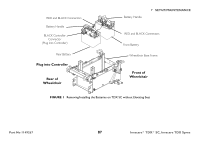
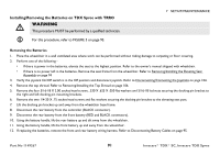
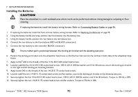
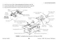
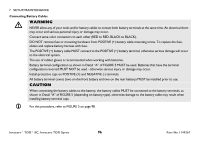
Installing/Removing the Batteries on TDX Spree with TRRO ƽ WARNING This procedure MUST be performed by a qualified technician. For this procedure, refer to FIGURE 3 on page 93. 7 SETUP/MAINTENANCE Removing the Batteries 1. Place the wheelchair in a well ventilated area where work can be performed without risking damage to carpeting or floor covering. 2. Perform one of the following - • If there is power in the batteries, elevate the seat to the highest position. Refer to the owner's manual shipped with wheelchair. • If there is no power left in the batteries, Remove the seat frame from the wheelchair. Refer to Removing/Installing the Elevating Seat Assembly on page 94 3. Verify the joystick On/Off switch is in the Off position and disconnect joystick. Refer to Disconnecting/Connecting the Joysticks on page 104. 4. Remove the top shroud. Refer to Removing/Installing the Top Shroud on page 106. 5. Remove the four 5/16-18 X 2.00 socket head screws, .330 X .625 X .050 flat washers and 5/16-18 locknuts securing the docking pin bracket to the right and left docking pin mounting brackets. 6. Remove the two 1/4-20 X .75 socket head screws and flat washers securing the docking pin bracket to the elevating seat post. 7. Lift the docking pin bracket up and away from the wheelchair base frame. 8. Disconnect the rear battery from the controller (BLACK connector). 9. Disconnect the rear battery from the front battery (RED and BLACK connectors). 10. Using the battery handle, lift the rear battery up and tilt away from the wheelchair. 11. Using the battery handle, lift the front battery up and away from the wheelchair. 12. If replacing the batteries, remove the front and rear battery wiring harness. Refer to Disconnecting Battery Cables on page 95. Part No 1149267 91 Invacare® TDX® SC, Invacare TDX Spree
-
 1
1 -
2
-
3
-
4
-
5
-
6
-
7
-
8
-
9
-
10
-
11
-
12
-
13
-
14
-
15
-
16
-
17
-
18
-
19
-
20
-
21
-
22
-
23
-
24
-
25
-
26
-
27
-
28
-
29
-
30
-
31
-
32
-
33
-
34
-
35
-
36
-
37
-
38
-
39
-
40
-
41
-
42
-
43
-
44
-
45
-
46
-
47
-
48
-
49
-
50
-
51
-
52
-
53
-
54
-
55
-
56
-
57
-
58
-
59
-
60
-
61
-
62
-
63
-
64
-
65
-
66
-
67
-
68
-
69
-
70
-
71
-
72
-
73
-
74
-
75
-
76
-
77
-
78
-
79
-
80
-
81
-
82
-
83
-
84
-
85
-
 86
86 -
 87
87 -
 88
88 -
 89
89 -
 90
90 -
 91
91 -
 92
92 -
 93
93 -
 94
94 -
 95
95 -
 96
96 -
97
-
98
-
99
-
100
-
101
-
102
-
103
-
104
-
105
-
106
-
107
-
108
-
109
-
110
-
111
-
112
-
113
-
114
-
115
-
116
 |
 |
