JVC RMP-2580U RM-P2580 Dome Controller Instructions (1148KB)
JVC RMP-2580U - Remote Controller For Color Domes Manual
 |
View all JVC RMP-2580U manuals
Add to My Manuals
Save this manual to your list of manuals |
JVC RMP-2580U manual content summary:
- JVC RMP-2580U | RM-P2580 Dome Controller Instructions (1148KB) - Page 1
R INTRODUCTION BASIC OPERATIONS APPLIED OPERATIONS REMOTE CONTROL UNIT CONNECTIONS RM-P2580 INSTRUCTIONS MENU SCREEN SETUPS OTHER For Customer Use: Enter below the Model No. and Serial No. which is located on the body. Retain this information for - JVC RMP-2580U | RM-P2580 Dome Controller Instructions (1148KB) - Page 2
. The exclamation point within an equilateral triangle is intended to alert the user to the presence of important operating and maintenance (servicing) instructions in the literature accompanying the appliance. Changes or modifications not approved by JVC could void the user's authority to operate - JVC RMP-2580U | RM-P2580 Dome Controller Instructions (1148KB) - Page 3
Thank you for purchasing the JVC RM-P2580. These instructions are for the RM-P2580U. CONTENTS 1. INTRODUCTION OPERATIONS ● CAMERA SELECTION ...10 ● POSITION SELECTION ...11 ● MANUAL OPERATION ...12 ● AUTO SEQUENCE OPERATION ...13 ● AUTO PAN 6. OTHER ● TROUBLESHOOTING ...33 ● SPECIFICATIONS ...34 3 - JVC RMP-2580U | RM-P2580 Dome Controller Instructions (1148KB) - Page 4
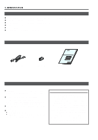
located on the body. Retain this information for future reference. Model No. Serial No. RM-P2580 Power cord (2 m) Ferrite Core Instructions (this manual) PRECAUTIONS FOR PROPER OPERATION Do not install the unit in a place subject to direct sunlight, excessive moisture, dust, or vibrations where - JVC RMP-2580U | RM-P2580 Dome Controller Instructions (1148KB) - Page 5
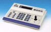
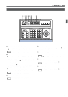
1. INTRODUCTION CONTROLS, CONNECTORS AND INDICATORS [Control Panel] 1 2 3 45 6 7 REMOTE CONTROL UNIT RM-P2580 CAMERA POSITION SETUP POWER SET MENU ALARM KEY LOCK AUTO F-1 F-2 F-3 LENS SPEED CAMERA/POSITION PAN/TILT POSITION 1 OPEN 2 5 8 0 /HOME 3 6 9 ENTER CAMERA CLOSE IRIS 4 7 - JVC RMP-2580U | RM-P2580 Dome Controller Instructions (1148KB) - Page 6
this control operation. For details, please consult your dealer or JVC-authorized service agent. REF. : "APPLIED SYSTEM (B MODE)" on page 22. lever in this direction to pan the rotary turret toward the left. REF. : "MANUAL OPERATION" on page 12. While a menu screen is displayed, this lever is used - JVC RMP-2580U | RM-P2580 Dome Controller Instructions (1148KB) - Page 7
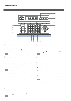
1. INTRODUCTION CONTROLS, CONNECTORS AND INDICATORS (Continued) $ [AUTO PATROL] button Press this button to switch the camera positions automatically in a preset order and at preset time intervals. POSITION ⁄ [FOCUS NEAR, FAR] FOCUS control buttons The POSITION display becomes as shown on the - JVC RMP-2580U | RM-P2580 Dome Controller Instructions (1148KB) - Page 8
1. INTRODUCTION CONTROLS, CONNECTORS AND INDICATORS (Continued) [Rear Panel] RX+ RX- TX+ TXRX RX TX TX TO CAMERA COM 1 2 3 4 5 6 7 8 DATA I / O UNIT CAMERA COM 9/1 10/2 11/3 12/4 13/5 14/6 15/7 16/8 COM AUTO ALARM COM SW COM SERIAL-1 SERIAL-2 POWER fi › ON OFF 1 2 3 4 VIDEO - JVC RMP-2580U | RM-P2580 Dome Controller Instructions (1148KB) - Page 9
2. BASIC OPERATIONS Manual Operation Camera Selection ( REF. :Page 10) Position Selection ( REF. : Page 11) Switching to the selected camera video. Switching the camera to the selected video position. - JVC RMP-2580U | RM-P2580 Dome Controller Instructions (1148KB) - Page 10
2. BASIC OPERATIONS CAMERA SELECTION Selecting a Desired Camera CAMERA display POSITION display 1. 2. Press the CAMERA button so that the indicator lights up. Input the camera number using the numeric keys (0 to 9). The input figure is shown in the CAMERA CAMERA display together with a period - JVC RMP-2580U | RM-P2580 Dome Controller Instructions (1148KB) - Page 11
. TK-C675BU: #0060 or after When the serial number of a camera is other than the above, please consult your nearest JVC-authorized service agent. Setting All Cameras to the Home Positions ( CAMERA display POSITION display REF. : Page 27 for the home position presetting.) 1. 2. F-3 Press the - JVC RMP-2580U | RM-P2580 Dome Controller Instructions (1148KB) - Page 12
camera and to control its lens. REMOTE CONTROL UNIT RM-P2580 CAMERA POSITION SETUP POWER WER SET MENU ALARM KEY LOCK AUTO F-1 F-2 F-3 NOTES ● Manual operation is not available in the AUTO SEQUENCE or AUTO PATROL modes. ● Only the lever tilting operation is available in the AUTO PAN mode - JVC RMP-2580U | RM-P2580 Dome Controller Instructions (1148KB) - Page 13
connector. The POSITION display shows the camera operation details. ( REF. : Page 10) NOTES ● During the AUTO SEQUENCE operation, the camera selection, manual selection, AUTO PAN operation and AUTO PATROL operation are not available. ● When the auto mode AUTO SEQUENCE operation is switched from ON - JVC RMP-2580U | RM-P2580 Dome Controller Instructions (1148KB) - Page 14
screen to perform the setting. As the rest of the setting procedure is variable depending on the camera models, please refer to the Instruction manual of the connected camera. CLOSE IRIS 4 7 CLEAR OPTION 1 OPTION 2 NEAR FOCUS AF FAR AUTO PAN AUTO PATROL WIDE ZOOM TELE AUTO PAN button - JVC RMP-2580U | RM-P2580 Dome Controller Instructions (1148KB) - Page 15
the setting. As the rest of the setting procedure is variable depending on the camera models, please refer to the instruction manual of the connected cameras. LENS SPEED CAMERA/POSITION PAN/TILT POSITION 1 OPEN 2 5 8 0 /HOME 3 6 9 ENTER 2. CAMERA CLOSE IRIS 4 7 CLEAR OPTION 1 OPTION - JVC RMP-2580U | RM-P2580 Dome Controller Instructions (1148KB) - Page 16
2. BASIC OPERATIONS KEY LOCK (PREVENTION OF OPERATION MISTAKE) The KEY LOCK function helps prevent operational mistakes by inhibiting the functions of all the buttons and the joystick on the control panel. KEY LOCK SET button indicator 1. REMOTE CONTROL UNIT RM-P2580 Press and hold the SET - JVC RMP-2580U | RM-P2580 Dome Controller Instructions (1148KB) - Page 17
the rear panel. The unit functions in either the ALARM PRIORITY mode or the MANUAL PRIORITY mode when an alarm signal is input. ( REF. : "CONTROL UNIT signal is received from a camera other than the camera being controlled manually, the alarm operation starts but, unlike in the alarm priority mode, - JVC RMP-2580U | RM-P2580 Dome Controller Instructions (1148KB) - Page 18
alarm condition continues until the preset position, of the camera to which the alarm signal was input, is selected. When the alarm signal is received by the camera currently being selected, the alarm operation can be stopped by pressing the ENTER button. If - JVC RMP-2580U | RM-P2580 Dome Controller Instructions (1148KB) - Page 19
the cameras must be synchronized). Set the system mode selection to A Mode, and set the rear DIP SW1 to "OFF". To set a camera ( REF. : Instructions Manual of the camera being used) · Match the ID with the VIDEO INPUT number. · Set to MULTIDOROP or DUPLEX Preset positions ( REF. : page 27) To change - JVC RMP-2580U | RM-P2580 Dome Controller Instructions (1148KB) - Page 20
video signal from the selected camera. Use the CAMERA SW input to switch the video signal and record it on the VCR. The preset operation, manual operation, AUTO PAN operation and AUTO PATROL operation are available for each camera. When fixed cameras are used, only the video signal can be switched - JVC RMP-2580U | RM-P2580 Dome Controller Instructions (1148KB) - Page 21
of the cameras must be synchronized) Set the system mode selection to B Mode, and set the rear DIP SW1 to "ON". To set a camera ( REF. : Instruction Manual of the camera being used) · Match the ID with the VIDEO INPUT number. · Set to MULTIDOROP and DUPLEX Using the SERIAL-2 item, set to the - JVC RMP-2580U | RM-P2580 Dome Controller Instructions (1148KB) - Page 22
alarm inputs is available by using the DATA I/O terminals. Alarms with up to 64 positions per camera can be handled via the SERIAL-1 connector. NOTES ● MANUAL operation of cameras and the menu operation are available even in the auto mode. ● As the frame switcher control signal is not output, the - JVC RMP-2580U | RM-P2580 Dome Controller Instructions (1148KB) - Page 23
4. CONNECTIONS REAR PANEL CONNECTORS TO CAMERA Connection to control the camera. (The RM-P2580 is compatible with a TK-C675B camera.) Communication is carried out by MULTIDROP FULL DUPLEX (RS-485, FULL DUPLEX). RM-P2580 CAMERA 1 RX+ RX- TX+ TX- R R T T X X X X + - + - A B C D A T X B T X C R - JVC RMP-2580U | RM-P2580 Dome Controller Instructions (1148KB) - Page 24
4. CONNECTIONS REAR PANEL CONNECTORS (Continued) DATA I/O REF. : "DATA I/O SCREEN" on page 30 for the input/output signal switching. COM 1 2 3 4 5 6 7 8 DATA I / O UNIT CAMERA COM 9/1 10/2 11/3 12/4 13/5 14/6 15/7 16/8 COM AUTO ALARM COM SW COM HOLD ALARM INPUTS 1 to 16 TTL level (Make/ - JVC RMP-2580U | RM-P2580 Dome Controller Instructions (1148KB) - Page 25
5. MENU SCREEN SETUPS FLOW OF MENUS For details of each screen, please refer to the reference pages 26 to 28. SET UP screen POSITION SETUP POSITION SETUP screen ( REF. : Page 27) CAMERA CAMERA screen ( REF. : Page 28) CONTROL UNIT screen ( REF. : Page 28) OPTION screen ( REF. : Page 29) MAX CAMERA - JVC RMP-2580U | RM-P2580 Dome Controller Instructions (1148KB) - Page 26
to operate. ● The alarm functions are disabled. ● The CAMERA SW is disabled. ● Remaining in operation are camera select, preset (home) position select, data output and manual control. Example of sub-menu screen after change (Displayed at A Mode Only) 26 - JVC RMP-2580U | RM-P2580 Dome Controller Instructions (1148KB) - Page 27
5. MENU SCREEN SETUPS POSITION SETUP SCREEN This screen is used to preset, correct or delete the camera positions. No position can be selected unless it has been preset. Up to 64 positions including the home position can be preset. Presetting and Correcting Camera Positions MENU button CAMERA - JVC RMP-2580U | RM-P2580 Dome Controller Instructions (1148KB) - Page 28
- JVC RMP-2580U | RM-P2580 Dome Controller Instructions (1148KB) - Page 29
Item PRIORITY Function Sets whether an alarm input is accepted during manual operation. ALARM : Alarm input is accepted even during manual operation. MANUAL : Alarm input is not accepted during manual operation. Options ALARM, MANUAL Default ALARM ALARM PRIORITY ALARM ALARM TIME 15SEC BUZZER TIME - JVC RMP-2580U | RM-P2580 Dome Controller Instructions (1148KB) - Page 30
TROUBLESHOOTING properly? ( REF. : Instruction manuals of the cameras in use.) set properly? ( REF. : Instruction manuals of the cameras in use.) • lens controls cannot be operated manually. Page 15 Page 29 Page problem still cannot be solved after following the above checks, please - JVC RMP-2580U | RM-P2580 Dome Controller Instructions (1148KB) - Page 31
6. OTHER SPECIFICATIONS Applicable cameras Max. cable length Control terminals : TK-C675B : 1.2 km : Push terminals (RS-485) 9600 bps. Video lines Number of inputs Level Number of outputs : 8 (BNC) : Composite, 1 V(p-p) : 2 (BNC) Max. number of connected cameras : 8 (A mode), 16(B mode) Max. - JVC RMP-2580U | RM-P2580 Dome Controller Instructions (1148KB) - Page 32
RM-P2580 REMOTE CONTROL UNIT R is a registered trademark owned by VICTOR COMPANY OF JAPAN, LTD. is a registered trademark in Japan, the U.S.A., the U.K. and many other countries. © 1999 VICTOR COMPANY OF JAPAN, LIMITED Printed in Japan SC96858-001
-
 1
1 -
 2
2 -
 3
3 -
 4
4 -
 5
5 -
 6
6 -
 7
7 -
8
-
9
-
10
-
11
-
12
-
13
-
14
-
15
-
16
-
17
-
18
-
19
-
20
-
21
-
22
-
23
-
24
-
25
-
26
-
27
-
28
-
29
-
30
-
31
-
32
 |
 |
INSTRUCTIONS
REMOTE CONTROL UNIT
RM-P2580
For Customer Use:
Enter below the Model No. and Serial
No. which is located on the body. Retain
this information for future reference.
Model No.
RM-P2580
Serial No.
SC96858-001
R
INTRODUCTION
BASIC OPERATIONS
APPLIED OPERATIONS
OTHER
CONNECTIONS
MENU SCREEN SETUPS