JVC RMP-2580U RM-P2580 Dome Controller Instructions (1148KB) - Page 31
JVC RMP-2580U - Remote Controller For Color Domes Manual
 |
View all JVC RMP-2580U manuals
Add to My Manuals
Save this manual to your list of manuals |
Page 31 highlights
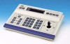
6. OTHER SPECIFICATIONS Applicable cameras Max. cable length Control terminals : TK-C675B : 1.2 km : Push terminals (RS-485) 9600 bps. Video lines Number of inputs Level Number of outputs : 8 (BNC) : Composite, 1 V(p-p) : 2 (BNC) Max. number of connected cameras : 8 (A mode), 16(B mode) Max. number of DATA I/O terminals : 16 Max. number of alarm inputs/outputs : 16 Number of UNIT ALARM outputs : 1 line (open-collector) Number of AUTO outputs Number of CAM SW circuits SERIAL-1 communication port SERIAL-2 communication port : 1 line (open-collector) :1 : RS-232C or RS-422A, 9600bps, D-sub connector (9-pin) : RS-232C or RS-422A, 9600bps, D-sub connector (9-pin) Other Supply voltage Power consumption Ambient temperatures Mass : AC100-120V : Approx. 3 W : (Operating) -10 to 50˚C (Recommended) 0 to 40˚C : Approx. 1.5 kn External Dimensions (Unit: mm) 240 REMOTE CONTROL UNIT RM-P2580 CAMERA POWER POWER SET ALARM KEY LOCK AUTO F-1 F-2 F-3 POSITION SETUP MENU LENS SPEED CAMERA/POSITION PAN/TILT 150 1 OPEN 2 5 8 0 /HOME 3 6 9 ENTER CAMERA POSITION CLOSE IRIS 4 7 CLEAR OPTION 1 OPTION 2 NEAR FOCUS AF FAR AUTO PAN AUTO PATROL 75.5 WIDE ZOOM TELE 202 300 53 (75) • Design and specifications are subject to change without notice. 34 26 203 ON AC POWER INPUT OFF RX+ RX- TX+ TXRX RX TX TX TO CAMERA ON 1 2 3 4 5 6 7 8 COM 1 1 1 2 3 4 5 2 2 6 7 8 DATA I / O UNIT CAMERA COM 9/1 10/2 11/3 12/4 13/5 14/6 15/7 16/8 COM AUTO ALARM COM SW COM 3 3 4 4 5 VIDEO OUTPUT VIDEO INPUT 5 6 6 7 7 SERIAL-1 8 8 SERIAL-2 MONITOR MONITOR OUTPUT OUTPUT 1 2 73 3
-
 1
1 -
2
-
3
-
4
-
5
-
6
-
7
-
8
-
9
-
10
-
11
-
12
-
13
-
14
-
15
-
16
-
17
-
18
-
19
-
20
-
21
-
22
-
23
-
24
-
25
-
 26
26 -
 27
27 -
 28
28 -
 29
29 -
 30
30 -
 31
31 -
 32
32
 |
 |
