JVC RMP-2580U RM-P2580 Dome Controller Instructions (1148KB) - Page 8
JVC RMP-2580U - Remote Controller For Color Domes Manual
 |
View all JVC RMP-2580U manuals
Add to My Manuals
Save this manual to your list of manuals |
Page 8 highlights
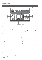
1. INTRODUCTION CONTROLS, CONNECTORS AND INDICATORS (Continued) [Rear Panel] RX+ RX- TX+ TXRX RX TX TX TO CAMERA COM 1 2 3 4 5 6 7 8 DATA I / O UNIT CAMERA COM 9/1 10/2 11/3 12/4 13/5 14/6 15/7 16/8 COM AUTO ALARM COM SW COM SERIAL-1 SERIAL-2 POWER fi › ON OFF 1 2 3 4 VIDEO INPUT 5 6 7 8 MONITOR MONITOR OUTPUT OUTPUT 1 2 AC`INPUT 1 2 3 4 5 6 7 8 , ¡ ON 1 2 3 4 5 VIDEO OUTPUT 6 7 8 ¢ £ ™ › [AC`INPUT] AC power input connector Connect to a conventional 120 V AC power supply using the provided power cord. , [MONITOR OUTPUT 1] Video signal output connector 1 Outputs the video signal selected with this unit. Connect to the video monitor, etc. This connector also outputs the video signal, which carries the on screen menu. fi [POWER] switch Turns the power of the unit ON and OFF. When this switch is set to ON, the POWER indicator 4 on the front panel lights up. ¡ [MONITOR OUTPUT 2] Video signal output connector 2 Connect to a time-lapse VCR, etc. The camera video signal output from this connector is switched according to the switching signal input at the CAMERA SW IN terminal ‡. When this unit is operated in the B mode ( REF. : Page 21): This connector outputs the same signal as the MONITOR OUTPUT 1 connector ,. fl [TO CAMERA] Camera control signal connectors Connection terminals for use in controlling the cameras. The control communications use the multi-drop, full-duplex communication system (RS-485). REF. :"REAR PANEL CONNECTORS (TO CAMERA)" on page 23. ‡ [DATA I/O] Data signal input/output terminals Connection terminals for use by the alarm input/output and select output signals. Connect the CAMERA SW terminal to a time-lapse VCR. REF. : "REAR PANEL CONNECTORS (DATA I/O)" on page 24. ™ [VIDEO INPUT] Video signal input connectors These connectors input the video signals from the cameras. When this unit is operated in the B mode, apply the output signal from a frame switcher to the VIDEO INPUT 1 connector. REF. :"BASIC SYSTEM" on page 19, "APPLIED SYSTEM" on page 21. ° [SERIAL-1] External extension connector 1 (D-sub 9-pin male connector) Use this connector when connecting an external component such as an alarm unit. REF. :"REAR PANEL CONNECTORS (SERIAL-1, -2)" on page 23. Contact your JVC sales agent for details. £ [VIDEO OUTPUT] Video signal output connectors Each of these connectors outputs the video signal corresponding to the VIDEO INPUT connector ™ above it. Connect these connectors to a video device such as a monitor. · [SERIAL-2] External extension connector 2 (D-sub 9-pin male connector) Use this connector when controlling a frame switcher (SWD7000/SW-D8000). REF. :"REAR PANEL CONNECTORS (SERIAL-1, -2)" on page 23. ¢ DIP switch Used to switch the system mode or the standard applied to the SERIAL-1 and -2 connectors. REF. :"REAR PANEL CONNECTORS (DIP SWITCH)" on page 23. 8
-
 1
1 -
2
-
 3
3 -
 4
4 -
 5
5 -
 6
6 -
 7
7 -
 8
8 -
 9
9 -
 10
10 -
 11
11 -
 12
12 -
 13
13 -
14
-
15
-
16
-
17
-
18
-
19
-
20
-
21
-
22
-
23
-
24
-
25
-
26
-
27
-
28
-
29
-
30
-
31
-
32
 |
 |
