JVC RMP-2580U RM-P2580 Dome Controller Instructions (1148KB) - Page 6
JVC RMP-2580U - Remote Controller For Color Domes Manual
 |
View all JVC RMP-2580U manuals
Add to My Manuals
Save this manual to your list of manuals |
Page 6 highlights
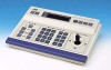
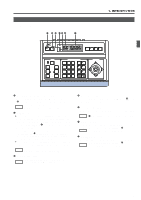
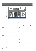
1. INTRODUCTION CONTROLS, CONNECTORS AND INDICATORS (Continued) 8 REMOTE CONTROL UNIT RM-P2580 CAMERA POWER POWER SET ALARM KEY LOCK AUTO F-1 F-2 F-3 POSITION SETUP MENU 9 0 LENS CAMERA/POSITION PAN/TILT POSITION ‹ ¤ ⁄ ) CLOSE NEAR SPEED 1 OPEN 2 5 8 0 /HOME 3 6 9 ENTER CAMERA IRIS 4 7 CLEAR OPTION 1 OPTION 2 ! @ # FOCUS AF FAR AUTO PAN AUTO PATROL WIDE ZOOM TELE ( * &^ % $ 8 [AUTO] button When this button is pressed, the unit enters the AUTO SEQUENCE mode, in which the indicator lights up and the MONITOR OUTPUT 1 connector , on the rear panel output the camera video signals according to automatic switching. REF. : "AUTO SEQUENCE OPERATION" on page 13. ! [POSITION] button Press when selecting one of the position numbers preset for the camera. To select a position, use the following buttons: POSITION button ! → Numeric key buttons * → ENTER button &. REF. : "POSITION SELECTION" on page 11. 9 [F1, F2, F3] Function buttons These buttons are valid only when SW-D7000/SW-D8000 frame switchers are being used. When this unit is operated in the B mode, these buttons can control certain functions of the specific frame switcher model connected to this unit. The RS-232C control is involved in this control operation. For details, please consult your dealer or JVC-authorized service agent. REF. : "APPLIED SYSTEM (B MODE)" on page 22. F1: Single-screen select switch Press this button to output a single-screen video from the frame switcher. The camera number can be selected using the numeric keypad, etc. F2: Split-screen select switch Press this button to output a split-screen video from the frame switcher. F3: LIVE/PLAY switch Press this button to switch between the playback video of a time-lapse VCR and the camera video. @ [OPTION 1, 2] These buttons are not used for the present. Do not touch them. # [PAN/TILT] control lever Operate the lever to pan (swing horizontally) or tilt (swing vertically) the rotary turret of a camera. 8(Up) : Tilt the lever in this direction to tilt the rotary turret upward. 9(Down) : Tilt the lever in this direction to tilt the rotary turret downward. ;(Right) : Tilt the lever in this direction to pan the rotary turret toward the right. :(Left) : Tilt the lever in this direction to pan the rotary turret toward the left. REF. : "MANUAL OPERATION" on page 12. While a menu screen is displayed, this lever is used to select or to set an item. REF. : "MENU OPERATION METHOD" on page 26. 0 [CAMERA] button Press when selecting a camera. To select a camera, use the following buttons: CAMERA button 0 → Numeric key buttons * → ENTER button &. REF. : "CAMERA SELECTION" on page 10. 6
-
 1
1 -
 2
2 -
 3
3 -
 4
4 -
 5
5 -
 6
6 -
 7
7 -
 8
8 -
 9
9 -
 10
10 -
 11
11 -
 12
12 -
13
-
14
-
15
-
16
-
17
-
18
-
19
-
20
-
21
-
22
-
23
-
24
-
25
-
26
-
27
-
28
-
29
-
30
-
31
-
32
 |
 |
