Konica Minolta PKG-675i PKG-675i User Manual
Konica Minolta PKG-675i Manual
 |
View all Konica Minolta PKG-675i manuals
Add to My Manuals
Save this manual to your list of manuals |
Konica Minolta PKG-675i manual content summary:
- Konica Minolta PKG-675i | PKG-675i User Manual - Page 1
OPERATION MANUAL DOCUMENT I 18.40V02 - Konica Minolta PKG-675i | PKG-675i User Manual - Page 2
/ Products Cautions on installation Information labels on PKG 675i Warning labels on PKG 675i PKG 675i Emergency stop PKG 675i Rearm 1. Before use 1.1. General Information 1.1.1. Manufacturer DOCUMENT I 18.40V02 - Update: 04.09.2019 OPERATIONAL MANUAL 5 5 5 5 5 5 6 7 8 8 10 11 12 14 17 19 - Konica Minolta PKG-675i | PKG-675i User Manual - Page 3
PKG 675i 2.1.2. PKG 675i packaged 2.1.3. PKG 675i unpackaged 2.1.4. PKG 675i assembled 2.1.5. PKG 675i packaged basket 2.1.6. PKG 675i unpackaged basket 2.2. Handling 2.2.1. PKG 675i Printhead DOCUMENT I 18.40V02 - Update: 04.09.2019 OPERATIONAL MANUAL 23 24 24 24 25 26 27 28 29 30 30 - Konica Minolta PKG-675i | PKG-675i User Manual - Page 4
Tray 4.10.2. Output Tray 5. Dismantling 5.1. Ink deprime - PKG 675i 5.2. Disassemble accessories 6. Maintenance 6.1. Maintenance table 6.2. Maintenance description 6.2.1. Cleaning 6.2.2. Software 6.2.3. Printhead Manual Cleaning 6.2.4. Internal Cleaning of the unit 6.2.5. Cleaning the - Konica Minolta PKG-675i | PKG-675i User Manual - Page 5
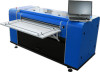
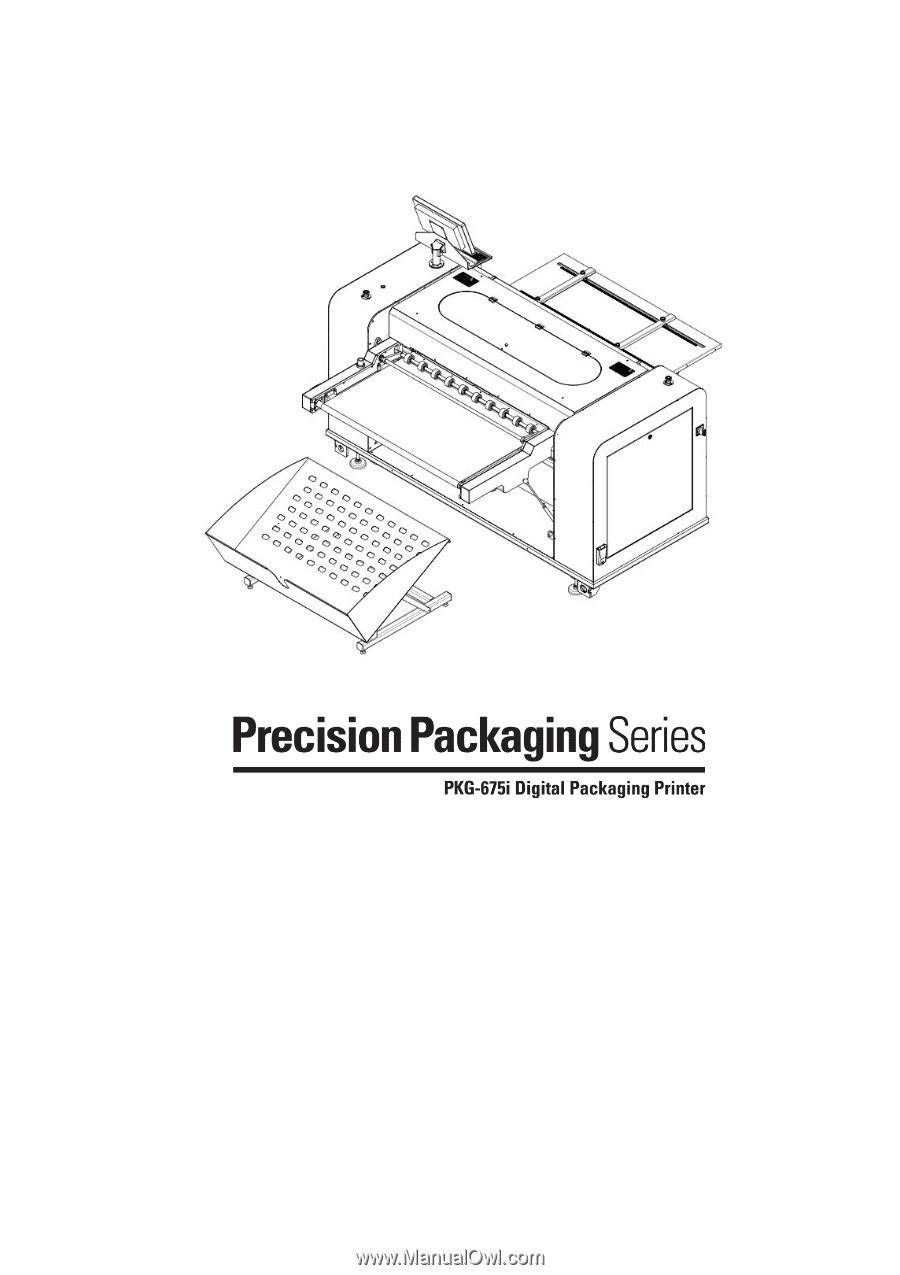
should be illegible due to destruction or lost by fire or breakage, purchase another copy of the Operation Manual from our office. FOREWORD The PKG 675i is a KM Cardboard Printer that prints on corrugated cardboard up to 1200 mm width (printable area width: 1060 mm), with water-based ink (4 colours - Konica Minolta PKG-675i | PKG-675i User Manual - Page 6
safe operate and prevent any damage to the PKG 675i and to the personnel that operating it. The indicated signs are used depending on the content of caution. Symbols and their meanings are given below. Please follow these instructions as you read this manual. SYMBOL MEANING Failure to observe the - Konica Minolta PKG-675i | PKG-675i User Manual - Page 7
MANUAL provided with the machine. Failure to observe those instructions may result in fire or electric shocks; • in fire or electric shocks. Contact your service representative for replacement cable; • Do not handle to the SPG (Site Preparation Guide document) and confirm that the machine is operating under - Konica Minolta PKG-675i | PKG-675i User Manual - Page 8
OPERATIONAL MANUAL HAZARDOUS MOVING PARTS • Keep fingers and other body parts away; • If a foreign object such as a small piece of metal or a liquid such as water gets inside the machine, turn off the machine and unplug the power cord immediately, then consult your service representative. Continuing - Konica Minolta PKG-675i | PKG-675i User Manual - Page 9
Consult with the local distributor or the KM main contacts (on this manual) about cleaning inside the equipment. Leaving the equipment with dust inside without may cause a fire or device failure. Consult with the distributor or service shop for the cost of cleaning inside the equipment; • To move - Konica Minolta PKG-675i | PKG-675i User Manual - Page 10
CAUTIONS AND NOTES OPERATIONAL MANUAL Handling of ink packs • The safety evaluation of this machine assumes that the ink recommended by this company is used. For safe usage of this - Konica Minolta PKG-675i | PKG-675i User Manual - Page 11
PRODUCTS TOOLS • Allen Key metric set; • Cutter; • Spirit level; • Cutting plier; • Nose plier; • Spanner set; • Wrench; • Measuring tape. OPERATIONAL MANUAL • Inner and outer hexagonal tool with metric measurement. PRODUCTS • Label off; • Alcohol; • Cleaning Fluid KM PH 50 ml; • WD40; • SKF LGMT - Konica Minolta PKG-675i | PKG-675i User Manual - Page 12
CAUTIONS ON INSTALLATION OPERATIONAL MANUAL • Failure to comply with the installation rules can result in injuries to personnel or damage to property. A place exposed to direct sunlight. On an inclined - Konica Minolta PKG-675i | PKG-675i User Manual - Page 13
OPERATIONAL MANUAL Around a place where fire is used. A place with much dust. A place with chemicals around. Use the machine under the following environmental conditions: The machine requires - Konica Minolta PKG-675i | PKG-675i User Manual - Page 14
OPERATIONAL MANUAL INFORMATION LABELS ON PKG 675I Information labels are stuck on the machine. Be sure to fully understand the information given on the labels. If one label is illegible due to - Konica Minolta PKG-675i | PKG-675i User Manual - Page 15
PKG 675I OPERATIONAL MANUAL DOCUMENT I 18.40V02 - Update: 04.09.2019 Page 15 - Konica Minolta PKG-675i | PKG-675i User Manual - Page 16
OPERATIONAL MANUAL DOCUMENT I 18.40V02 - Update: 04.09.2019 Page 16 - Konica Minolta PKG-675i | PKG-675i User Manual - Page 17
OPERATIONAL MANUAL WARNING LABELS ON PKG 675I Warning labels are stuck on the machine. Be sure to fully understand the warning given on the labels. If a warning label is illegible due to stains or has come off, purchase a new one from a distributor or our sales office. LABELS PKG 675I Danger: - Konica Minolta PKG-675i | PKG-675i User Manual - Page 18
OPERATIONAL MANUAL DOCUMENT I 18.40V02 - Update: 04.09.2019 Page 18 - Konica Minolta PKG-675i | PKG-675i User Manual - Page 19
OPERATIONAL MANUAL PKG 675I EMERGENCY STOP The PKG 675i machine is equipped with two safety devices, which allows the operator to terminate immediately all machine operations whenever it deems that are not met all - Konica Minolta PKG-675i | PKG-675i User Manual - Page 20
OPERATIONAL MANUAL PKG 675I REARM After the emergency button has been pressed the PKG 675i software will look like this: STEP 1: To rearm release the emergency button pressed. Turn the button in the direction indicated by the arrow. DOCUMENT I 18.40V02 - Update: 04.09.2019 Page 20 - Konica Minolta PKG-675i | PKG-675i User Manual - Page 21
STEP 2: Go to the PKG 675i software and select Rearm. OPERATIONAL MANUAL The PKG 675i is now ready to print again. DOCUMENT I 18.40V02 - Update: 04.09.2019 Page 21 - Konica Minolta PKG-675i | PKG-675i User Manual - Page 22
OPERATIONAL MANUAL OPERATION MANUAL DOCUMENT I 18.40V02 - Update: 04.09.2019 Page 22 - Konica Minolta PKG-675i | PKG-675i User Manual - Page 23
: Company name Mtex New Solution, SA Contacts Address Rua Academia FC Famalicão, PAV. 17 4760-482 Esmeriz Vila Nova de Famalicão, Portugal 1.1.2. Machine plate 1.1.2.1. PKG 675i OPERATIONAL MANUAL Email [email protected] Phone +351 252 371 109 DOCUMENT I 18.40V02 - Update: 04.09.2019 Page 23 - Konica Minolta PKG-675i | PKG-675i User Manual - Page 24
2. EQUIPMENT SPECIFICATIONS 2.1. Dimensions and weight of the standard configurations 2.1.1. PKG 675i OPERATIONAL MANUAL Height 1591 mm || 5.22 ft. Width 2410 mm || 7.91 ft. Depth Weight 2279 mm || 7.48 ft. 1010 kg || 2227 lbs. DOCUMENT I 18.40V02 - Update: 04.09.2019 Page 24 - Konica Minolta PKG-675i | PKG-675i User Manual - Page 25
2.1.2. PKG 675i packaged OPERATIONAL MANUAL Height 1397 mm || 4.58 ft. Width 2460 mm || 8.07 ft. Depth Weight 1230 mm || 4.04 ft. 1100 kg || 2425 lbs. DOCUMENT I 18.40V02 - Update: 04.09.2019 Page 25 - Konica Minolta PKG-675i | PKG-675i User Manual - Page 26
2.1.3. PKG 675i unpackaged OPERATIONAL MANUAL Height 1264 mm || 4.09 ft. Width 2410 mm || 7.91 ft. Depth Weight 1150 mm || 3.77 ft. 1010 kg || 2227 lbs. DOCUMENT I 18.40V02 - Update: 04.09.2019 Page 26 - Konica Minolta PKG-675i | PKG-675i User Manual - Page 27
2.1.4. PKG 675i assembled OPERATIONAL MANUAL Height 1630 mm || 5.35 ft Width Depth Weight 2410 mm || 7.91 ft. 3260 mm || 10.70 ft 1060 kg || 2337 lbs. DOCUMENT I 18.40V02 - Update: 04.09.2019 Page 27 - Konica Minolta PKG-675i | PKG-675i User Manual - Page 28
2.1.5. PKG 675i packaged basket OPERATIONAL MANUAL Height 732 mm || 2.40 ft. Width 1300 mm || 4.27 ft. Depth 995 mm || 3.26 ft. Weight 75kg || 165.3 lbs. DOCUMENT I 18.40V02 - Update: 04.09.2019 Page 28 - Konica Minolta PKG-675i | PKG-675i User Manual - Page 29
2.1.6. PKG 675i unpackaged basket OPERATIONAL MANUAL Height 615 mm || 2.02 ft. Width 1254 mm || 4.11 ft. Depth 1022 mm || 3.35 ft. Weight 50 kg || 110.2 lbs. DOCUMENT I 18.40V02 - Update: 04.09.2019 Page 29 - Konica Minolta PKG-675i | PKG-675i User Manual - Page 30
2.2. Handling 2.2.1. PKG 675i - gravity centre OPERATIONAL MANUAL DOCUMENT I 18.40V02 - Update: 04.09.2019 Page 30 - Konica Minolta PKG-675i | PKG-675i User Manual - Page 31
OPERATIONAL MANUAL DOCUMENT I 18.40V02 - Update: 04.09.2019 Page 31 - Konica Minolta PKG-675i | PKG-675i User Manual - Page 32
OPERATIONAL MANUAL 2.3. Electrical connection requirements Version 2.2 • Machine power: Plug CEE 7/7 (1P+N+E Male 16 Amp.); • Installation power: Socket Type F (1P+N+E Female 16 Amp.); • Machine main circuit protection: Differential - Konica Minolta PKG-675i | PKG-675i User Manual - Page 33
: AIR HOSE SPECIFICATIONS Inside diameter 5 mm Outside diameter 8 mm Bend radius 15 mm • The air hose connector is provided by us. OPERATIONAL MANUAL • It is the customer's responsibility to ensure that the air used in the machine is clean and dry. 2.6. Connections DOCUMENT I 18.40V02 - Konica Minolta PKG-675i | PKG-675i User Manual - Page 34
OPERATIONAL MANUAL 2.7. Recommended environment The machine requires an area with enough space for the material to be easily carried or loaded onto the machine without hindering its - Konica Minolta PKG-675i | PKG-675i User Manual - Page 35
OPERATIONAL MANUAL 2.9. Minimum workspace requirements & workstation The machine requires an area with enough space for the material to be easily carried or loaded onto the machine without - Konica Minolta PKG-675i | PKG-675i User Manual - Page 36
3. MAIN FEATURES 3.1. PKG 675i main features OPERATIONAL MANUAL DOCUMENT I 18.40V02 - Update: 04.09.2019 Page 36 - Konica Minolta PKG-675i | PKG-675i User Manual - Page 37
OPERATIONAL MANUAL 4. EQUIPMENT SETUP 4.1. Unpacking procedure Step 1: Remove the yellow unit ft.) measure long; Prior to lowering the machine onto the ground, please ensure that the supporting legs are still in the "up" position, to prevent damage when moving. DOCUMENT I 18.40V02 - Update: 04 - Konica Minolta PKG-675i | PKG-675i User Manual - Page 38
OPERATIONAL MANUAL Loosen the screws and remove all four yellow holders that fix the unit to the base of the crate. Place the unit carefully on the floor. Adjust the position of the Basket according to the Machine position. Please check the PKG 675i assemble of this document. DOCUMENT I 18.40V02 - - Konica Minolta PKG-675i | PKG-675i User Manual - Page 39
OPERATIONAL MANUAL 4.2. Assembling PKG 675i with the Take-up 4.2.1. Levelling The PKG 675i is equipped with four wheels each, equipped for light movement (like seen in the left picture). These wheels can't be used to push the press - Konica Minolta PKG-675i | PKG-675i User Manual - Page 40
OPERATIONAL MANUAL DOCUMENT I 18.40V02 - Update: 04.09.2019 Page 40 - Konica Minolta PKG-675i | PKG-675i User Manual - Page 41
OPERATIONAL MANUAL 4.2.2. Accessories Assembling 4.2.2.1. PSL 675i: Swing arm system and LCD Screen When preparing to install the LCD screen, firstly remove and open all the peripherals placed within the boxes. Install - Konica Minolta PKG-675i | PKG-675i User Manual - Page 42
OPERATIONAL MANUAL 4.2.3. Plug the power cable The PKG 675i has three connections as shown before and below. Make sure that all connections are made before turning on the Power Switch. Do NOT turn on the printer at this moment. DOCUMENT I 18.40V02 - Update: 04.09.2019 Page 42 - Konica Minolta PKG-675i | PKG-675i User Manual - Page 43
OPERATIONAL MANUAL 4.3. Installing the ink tanks The printer uses CMYK ink tanks, each one contains two or ten litres of ink when opened. Every ink tank is - Konica Minolta PKG-675i | PKG-675i User Manual - Page 44
STEP 2: Remove the ink tanks from their protective boxes/plastic bagging OPERATIONAL MANUAL STEP 3: Remove the orange protective cover Verify that the protective cover was not removed before. If you see any sign of violation of the protective - Konica Minolta PKG-675i | PKG-675i User Manual - Page 45
OPERATIONAL MANUAL STEP 4: Ensure that you insert the ink tube into the box first, followed by the data cable. DOCUMENT I 18.40V02 - Update: 04.09.2019 Page 45 - Konica Minolta PKG-675i | PKG-675i User Manual - Page 46
OPERATIONAL MANUAL STEP 5: The couplings can only be connected in their correspondent color. It is not possible to couple in a different way. Be sure you install all ink colours (CMYK + K) on their correct position. DOCUMENT I 18.40V02 - Update: 04.09.2019 Page 46 - Konica Minolta PKG-675i | PKG-675i User Manual - Page 47
OPERATIONAL MANUAL 4.4. Turn the power on The main switch is located on the back side of the machine. Set the main power switch ON. DOCUMENT I 18.40V02 - Update: 04.09.2019 Page 47 - Konica Minolta PKG-675i | PKG-675i User Manual - Page 48
printhead, please follow the steps below: STEP 1: Unpack the printhead a) Open the printhead package outer box and slide out the foil bag; OPERATIONAL MANUAL Inspect the integrity of the foil vacuum sealing. The foil bag should be formed tightly to the contours of the printhead cartridge as shown - Konica Minolta PKG-675i | PKG-675i User Manual - Page 49
OPERATIONAL MANUAL e) Remove the protective strip from the electrical contacts. While holding the printhead cartridge by the handle with one hand, grasp the pull tab with the - Konica Minolta PKG-675i | PKG-675i User Manual - Page 50
OPERATIONAL MANUAL f) Remove the protective strip from the printhead nozzles. While holding the printhead cartridge by the handle with one hand, grasp the pull tab with the - Konica Minolta PKG-675i | PKG-675i User Manual - Page 51
OPERATIONAL MANUAL STEP 2: Installing the printhead a) While having the error message above ("Printhead might be missing"), open the top cover on PKG 675i to gain access to the print engine; b) If the latch is released open the printhead latch all the way up; Printhead latch Opening If the - Konica Minolta PKG-675i | PKG-675i User Manual - Page 52
OPERATIONAL MANUAL c) Insert the printhead by the handle into the cradle and pull it backwards until it snaps into the proper place standing upright; d) Close the printhead - Konica Minolta PKG-675i | PKG-675i User Manual - Page 53
OPERATIONAL MANUAL 4.6. Initial ink prime STEP 1: To confirm that all the ink tanks were properly installed, please confirm on the PKG 675i software (Notifications section) that you have 5 "RECOVERABLE ERROR PRINTHEAD" errors. STEP 2: On the KM software please select "INITIAL FILL AND PRIME". - Konica Minolta PKG-675i | PKG-675i User Manual - Page 54
The ink tubes circuit will start being filled up with ink. OPERATIONAL MANUAL STEP 3: On the KM software you will have no error notifications and the ink level will be full. Machine is now ready to start printing. DOCUMENT I 18.40V02 - Update: 04.09.2019 Page 54 - Konica Minolta PKG-675i | PKG-675i User Manual - Page 55
OPERATIONAL MANUAL 4.7. Ripped on CALDERA Before printing the job, it is necessary to prepare the file through Caldera software. Switch to the Linux system and in the main menu click on "Fileman". DOCUMENT I 18.40V02 - Update: 04.09.2019 Page 55 - Konica Minolta PKG-675i | PKG-675i User Manual - Page 56
In the "Fileman" box, look for the file to edit. OPERATIONAL MANUAL DOCUMENT I 18.40V02 - Update: 04.09.2019 Page 56 - Konica Minolta PKG-675i | PKG-675i User Manual - Page 57
When you find the file, select and open it. OPERATIONAL MANUAL Click on "NS MULTI". DOCUMENT I 18.40V02 - Update: 04.09.2019 Page 57 - Konica Minolta PKG-675i | PKG-675i User Manual - Page 58
OPERATIONAL MANUAL The file is read by the system that assumes the dimensions and remaining technical characteristics of the file. Click on "Image positioning and scale setting on the page". Click on "Print". DOCUMENT I 18.40V02 - Update: 04.09.2019 Page 58 - Konica Minolta PKG-675i | PKG-675i User Manual - Page 59
Naming the file and click on "ok". OPERATIONAL MANUAL The process with Caldera software is finished. DOCUMENT I 18.40V02 - Update: 04.09.2019 Page 59 - Konica Minolta PKG-675i | PKG-675i User Manual - Page 60
4.8. Print process STEP 1: Check the thickness of the cardboard that will be used. OPERATIONAL MANUAL The cardboard thickness should be measured before with precision. A wrong measure can damage the printheads. Please check the media characteristics that can be use on - Konica Minolta PKG-675i | PKG-675i User Manual - Page 61
OPERATIONAL MANUAL STEP 2: On the KM Software please change the "HEAD HEIGHT" with the correct cardboard thickness measured and press ok. STEP 3: Adjust the cardboard on the input tray centred with both sides tray rulers. DOCUMENT I 18.40V02 - Update: 04.09.2019 Page 61 - Konica Minolta PKG-675i | PKG-675i User Manual - Page 62
OPERATIONAL MANUAL Use the "Arrow" (zero centre) on the machine Input Tray to adjust the cardboard as much precise as possible. STEP 4: With the cardboard on the - Konica Minolta PKG-675i | PKG-675i User Manual - Page 63
STEP 5: On the KM software, select from the library the file to be printed. OPERATIONAL MANUAL All listed files on the software library were previously ripped on CALDERA: STEP 6: A file preview is now on the software layout to confirm that the - Konica Minolta PKG-675i | PKG-675i User Manual - Page 64
STEP 7: Fill the "PRINT" box with the number of copies to print. OPERATIONAL MANUAL STEP 8: Select Print and the software will show the message "PRE-PRINT". DOCUMENT I 18.40V02 - Update: 04.09.2019 Page 64 - Konica Minolta PKG-675i | PKG-675i User Manual - Page 65
STEP 9: The PKG 675i will start printing after the "PRE-PRINTING" process. OPERATIONAL MANUAL DOCUMENT I 18.40V02 - Update: 04.09.2019 Page 65 - Konica Minolta PKG-675i | PKG-675i User Manual - Page 66
4.9. Remove and install Printhead and Wiper 4.9.1. Remove and install Printhead OPERATIONAL MANUAL When installing a new printhead you should also install a new wiper on the Service Station. To remove a printhead go to the menu CONTROLS / HEADS and select which printhead is going to be removed. - Konica Minolta PKG-675i | PKG-675i User Manual - Page 67
After selecting the printhead to uninstall click on REMOVE PRINTHEAD. OPERATIONAL MANUAL The latch of the printhead is released and the operator must remove the printhead and store it properly in the original protections. DOCUMENT I 18.40V02 - Update: 04.09.2019 Page 67 - Konica Minolta PKG-675i | PKG-675i User Manual - Page 68
OPERATIONAL MANUAL DOCUMENT I 18.40V02 - Update: 04.09.2019 Page 68 - Konica Minolta PKG-675i | PKG-675i User Manual - Page 69
OPERATIONAL MANUAL DOCUMENT I 18.40V02 - Update: 04.09.2019 Page 69 - Konica Minolta PKG-675i | PKG-675i User Manual - Page 70
OPERATIONAL MANUAL From here repeat the procedure STEP 1 of the chapter Installing total printhead and ink system. After that, installing the new printhead: a) While having the error message above ("Printhead might be missing"), open the top cover on PKG 675i to gain access to the print engine; - Konica Minolta PKG-675i | PKG-675i User Manual - Page 71
Open the printhead latch to place the printhead cartridge. OPERATIONAL MANUAL DOCUMENT I 18.40V02 - Update: 04.09.2019 Page 71 - Konica Minolta PKG-675i | PKG-675i User Manual - Page 72
OPERATIONAL MANUAL Go to: CONTROLS/ HEADS/ INSTALL PRINTHEAD. Wait for the printhead installation time and the machine is ready to print again. DOCUMENT I 18.40V02 - Update: 04.09.2019 Page 72 - Konica Minolta PKG-675i | PKG-675i User Manual - Page 73
Remove the Wiper To do this, go to: CONTROLS / REMOVE SERVICE STATION WIPER. OPERATIONAL MANUAL Menu: Controls / Remove Service Station Wiper Go to: CONTROLS / OPEN PRINTHEAD. After this instruction the print module opens, and the manual replacement can be performed. Wiper Grasp the MFR near one - Konica Minolta PKG-675i | PKG-675i User Manual - Page 74
OPERATIONAL MANUAL Obtain a new MFR and remove the protective plastic cover by peeling along the the end with the ratchet mounted to it is placed to the left. Starting at the left end of the Service Station carousel, place the left end of the MFR at the entrance to the holder. Note the position of - Konica Minolta PKG-675i | PKG-675i User Manual - Page 75
OPERATIONAL MANUAL 4.10. Manometers Pinches The PKG 675i has 2 manometers. Each manometer has 4 pinches. The manometer in the cardboard entry zone has 2 pinches on its side and 2 on the left side of the - Konica Minolta PKG-675i | PKG-675i User Manual - Page 76
4.10.1. Input Tray OPERATIONAL MANUAL In this case, in order to get access to the pinches of the same side of the manometer, access the right-side door of the machine. DOCUMENT I 18.40V02 - Update: 04.09.2019 Page 76 - Konica Minolta PKG-675i | PKG-675i User Manual - Page 77
OPERATIONAL MANUAL 4.10.2. Output Tray STEP 1: While the output tray is still lifted uninstall the left side cover of the tray unscrewing 8 screws. After remove the side cover you can make the necessary adjustments to the pinches of the output tray. DOCUMENT I 18.40V02 - Update: 04.09.2019 Page 77 - Konica Minolta PKG-675i | PKG-675i User Manual - Page 78
5. DISMANTLING OPERATIONAL MANUAL This process must be carried out by a specialized technician and certified by KM. 5.1. Ink deprime - PKG 675i To run the process the unit must be without any work going on. To change the location where the machine is installed, a set of procedures - Konica Minolta PKG-675i | PKG-675i User Manual - Page 79
OPERATIONAL MANUAL DEPRIME ON This procedure allows to remove all ink from the system. When this task is complete press "Remove Printhead". The printheads can also be - Konica Minolta PKG-675i | PKG-675i User Manual - Page 80
OPERATIONAL MANUAL STEP 2: After STEP 1 is completed the latches of the printheads are released. The operator must remove each one and store properly in the original protections. DOCUMENT I 18.40V02 - Update: 04.09.2019 Page 80 - Konica Minolta PKG-675i | PKG-675i User Manual - Page 81
OPERATIONAL MANUAL DOCUMENT I 18.40V02 - Update: 04.09.2019 Page 81 - Konica Minolta PKG-675i | PKG-675i User Manual - Page 82
OPERATIONAL MANUAL DOCUMENT I 18.40V02 - Update: 04.09.2019 Page 82 - Konica Minolta PKG-675i | PKG-675i User Manual - Page 83
STEP 3: Turn OFF the machine. STEP 4: Remove the ink cartridges (protect with the original protections). OPERATIONAL MANUAL No process should be skipped or executed before the previous sequential process has been correctly executed. 5.2. Disassemble accessories Consult the Accessories Assembling - Konica Minolta PKG-675i | PKG-675i User Manual - Page 84
50ml). Waste bottle cleaning cleared. (6.2.8.) General inspection for ink leaks (reservoir, tubing, fittings, etc.). Lubrication of the motor shaft bearings (SKF LGMT 2/0.4). Daily Moi OPERATIONAL MANUAL Weekly 3 Months DOCUMENT I 18.40V02 - Update: 04.09.2019 Page 84 - Konica Minolta PKG-675i | PKG-675i User Manual - Page 85
6.2. Maintenance description OPERATIONAL MANUAL • Wear always protective clothes and footwear. 6.2.1. Cleaning The full unit should be kept clean to prevent the accumulation of external waste (dust and dirt) which - Konica Minolta PKG-675i | PKG-675i User Manual - Page 86
to the printing area and to the printheads. Next, with a lint free cloth and distilled water, make a smooth clean over each printhead. Printhead Manual Cleaning This process must be done in the shortest possible time so that the printheads are exposed to atmospheric air for the shortest possible - Konica Minolta PKG-675i | PKG-675i User Manual - Page 87
6.2.4. Internal Cleaning of the unit Go to the Menu: CONTROLS / OPEN PRINTHEAD OPERATIONAL MANUAL Printhead Manual Cleaning It is necessary to ensure that dust and particles of accumulated ink dust are removed which, in the medium term, can damage components of - Konica Minolta PKG-675i | PKG-675i User Manual - Page 88
OPERATIONAL MANUAL 6.2.5. Cleaning the Station Each printhead has a service station composed of three to: CONTROLS / OPEN PRINTHEAD. Menu: Controls / Printhead After this instruction, the print module opens, and the manual cleaning can be performed. Capping of the printheads exposed to do cleaning - Konica Minolta PKG-675i | PKG-675i User Manual - Page 89
part of the service station can accumulate waste and therefore a regular inspection is required. To clean the platens, go to: CONTROLS / CLEAN PLATENS. Menu: Controls / Clean Platens Click on: CONTROLS / OPEN PRINTHEAD. After this instruction the print module opens, and the manual cleaning can be - Konica Minolta PKG-675i | PKG-675i User Manual - Page 90
OPERATIONAL MANUAL To finish the process, go to: CONTROLS / CLOSE PRINTHEAD and after that click on "FINISH CLEANING PLATEN". Menu: Controls / Finish Cleaning Platens The third is the wiper cleaning position which corresponds to the micro fibre roller belonging to each service station of the - Konica Minolta PKG-675i | PKG-675i User Manual - Page 91
/ OPEN PRINTHEAD. After this instruction the print module opens, and the manual cleaning can be performed. Wiper After the cleaning go to: CONTROLS / CLOSE PRINTHEAD and after that click on "FINISH WETTING SERVICE STATION WIPER". Controls / Finish Wetting Service Station Wiper It is necessary to - Konica Minolta PKG-675i | PKG-675i User Manual - Page 92
register to the system. To clean the Media Encoder, go to: CONTROLS / OPEN PRINTHEAD. Menu: Controls / Printhead After this instruction, the print module opens, and the manual cleaning can be performed. STEP 1: Unscrew the 2 screws and gently undock the Media Encoder. DOCUMENT I 18.40V02 - Update - Konica Minolta PKG-675i | PKG-675i User Manual - Page 93
STEP 2: Extra carefully, undock all the cables switch. OPERATIONAL MANUAL STEP 3: Unscrew the two screws holding the encoder reader and clean the remaining frame with a lint free cloth and distilled water. DOCUMENT I 18.40V02 - Update: 04.09.2019 Page 93 - Konica Minolta PKG-675i | PKG-675i User Manual - Page 94
OPERATIONAL MANUAL 6.2.7. No crush wheels The no crush wheels may accumulate some ink. It is necessary to inspect and clean them so that they do not mark - Konica Minolta PKG-675i | PKG-675i User Manual - Page 95
Safety-related inspections OPERATIONAL MANUAL Action PKG 675i Open main doors PKG 675i Activate the emergency button PKG 675i Open the ink door Daily Weekly Monthly 3 Months Right after you perform the emergency test described, access the software on the PKG 675i interface and click "Rearm - Konica Minolta PKG-675i | PKG-675i User Manual - Page 96
OPERATIONAL MANUAL 7. USER INTERFACE (UI) 7.1. Disclaimer Our User Interface was fully developed by KM's brand and can only be used in the machines manufactured by KM. All - Konica Minolta PKG-675i | PKG-675i User Manual - Page 97
7.2.1. Main menu OPERATIONAL MANUAL This menu allows you to access the different sub-menus in the UI (all the menus will be explained in detail later in this chapter). 7.2.2. - Konica Minolta PKG-675i | PKG-675i User Manual - Page 98
7.2.4. Head height OPERATIONAL MANUAL This menu informs of what is the head height defined by the user for the media used 7.2.5. Ink information This menu informs the overall ink system supply levels of the ink tanks and the intermediate tanks. DOCUMENT I 18.40V02 - Update: 04.09.2019 Page 98 - Konica Minolta PKG-675i | PKG-675i User Manual - Page 99
7.2.6. Job It's where the print images (jobs) are with a search option available. OPERATIONAL MANUAL 7.2.7. Sub-menus In the Sub-menus, it is possible to access controls and change settings and also return to the "home" menu. DOCUMENT I 18.40V02 - Update: 04.09.2019 Page 99 - Konica Minolta PKG-675i | PKG-675i User Manual - Page 100
7.2.8. Controls a) General Menu OPERATIONAL MANUAL Open Printhead: Opens the Top Head System; Access Ink Tanks - Used to change inks; Reset Graphcet - Reset's machine services in case of error; Printhead Alignment - Perform the Printhead alignment procedure; Initial Fill and Prime - Perform the - Konica Minolta PKG-675i | PKG-675i User Manual - Page 101
b) Heads menu OPERATIONAL MANUAL Heads - Select which head you need to control (from All to separate the ink fill procedure on the specified printhead); Remove Service Station Wiper -Position the cleaning station for wiper removal; Install Service Station Wiper - After the new wiper install, it - Konica Minolta PKG-675i | PKG-675i User Manual - Page 102
of the print engine (media thickness) in millimeters; Override Sheet Length - Overrides the value of the sheet length; Sheet length - Where to put manually the length of the sheet to be printed. c) Printer Stall Detection - If enabled, will allow print engine to detect stalls over the media encoder - Konica Minolta PKG-675i | PKG-675i User Manual - Page 103
OPERATIONAL MANUAL This is a crucial setup to get good printing results on different materials. Each material must have an associated "RSM" value. The height of the card - Konica Minolta PKG-675i | PKG-675i User Manual - Page 104
d) Maintenance OPERATIONAL MANUAL Post Print Cap Delay (sec) - Post-print wait time, i.e. mm) - Length in mm/inches/mil printed before a service break; Auto Service Page Count Trigger - How many pages before an auto recovery is run; Auto Service Length Trigger (mm) - in mm/inches/mil printed before - Konica Minolta PKG-675i | PKG-675i User Manual - Page 105
7.2.10. Floating app OPERATIONAL MANUAL This menu will be enable everywhere in the UI. It allows to shut down Floating app actions: 1- Shutdown the machine; 2- Cancel job; 3- Clear errors; 4- TeamViewer; 5- Restart printer; 6- Restart services. DOCUMENT I 18.40V02 - Update: 04.09.2019 Page 105 - Konica Minolta PKG-675i | PKG-675i User Manual - Page 106
OPERATIONAL MANUAL 8. TROUBLESHOOTING Every time the printer has an error, a message will appear contact your supplier. EtherCAT network error Check the connections between the slaves. There is a problem with the EtherCAT Clear the errors using the function available in the UI. network. Power - Konica Minolta PKG-675i | PKG-675i User Manual - Page 107
OPERATIONAL MANUAL Laminator's feed emergency stop The laminator's feed emergency button is If there is no longer a reason for it to be pressed, release the currently being - Konica Minolta PKG-675i | PKG-675i User Manual - Page 108
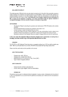
8.2. Troubleshooting Issue Description / Solution Skew 42x24 Used to determine the 'Skew' performance of the - 40.58" (1,026.7mm - 1,030.7mm). CMYK Bars Used to evaluate general nozzle health and printhead performance. OPERATIONAL MANUAL Image DOCUMENT I 18.40V02 - Update: 04.09.2019 Page 108 - Konica Minolta PKG-675i | PKG-675i User Manual - Page 109
these printheads. The Media Encoder Handoff transition is only meaningful in the context of printing from PHs 0, 2 & 4. DOCUMENT I 18.40V02 - Update: 04.09.2019 OPERATIONAL MANUAL Page 109 - Konica Minolta PKG-675i | PKG-675i User Manual - Page 110
OPERATIONAL MANUAL Issue Description / Solution Image Vertical White Lines are classified into three (3) categories: • White Lines (General) • Remove and reseat the printhead; • Replace printhead if problem persists; • Medium - suspected cause is dehydration: • Dehydration is often resolved by - Konica Minolta PKG-675i | PKG-675i User Manual - Page 111
the Printhead Cartridge that requires replacement of the PHC. Solution Follow these steps to diagnose and troubleshoot this issue: • Remove the Printhead Cartridge from the Print Engine (PE); • Inspect the the board will DOCUMENT I 18.40V02 - Update: 04.09.2019 OPERATIONAL MANUAL Page 111 - Konica Minolta PKG-675i | PKG-675i User Manual - Page 112
Cartridge to the PE; • If the problem persists, replace the printhead with a new one. OPERATIONAL MANUAL Print Quality (PQ) Defects Missing Jets A level 3" servicing routine on the printhead that is exhibiting the defect. Confirm that the defect has been corrected. If the problem persists, - Konica Minolta PKG-675i | PKG-675i User Manual - Page 113
be caused by a number of reasons including inadequate Printhead maintenance by the Service Station, or the presence of paper fibers that block nozzles. Solution seconds after the completion of a print job. If the problem is a persistent one, then perform a "level 2 recovery". DOCUMENT I 18. - Konica Minolta PKG-675i | PKG-675i User Manual - Page 114
acts to suck this ink into the nozzles. Solution The automatic servicing routines are designed to prevent Color Mixing. If this defect is Color Mixing as the system exits the "Cap" state. If the problem persists, then perform a 'recovery level 2' to expel the cross-color OPERATIONAL MANUAL Page 114 - Konica Minolta PKG-675i | PKG-675i User Manual - Page 115
reported by the PE firmware, refer to section 'Troubleshooting the Waste Ink Pumps'. Print Quality (PQ) Defects the 'Printhead Alignment' procedure. If the problem persists, then verify that the Post-Grit sensor is clean and functioning properly. OPERATIONAL MANUAL DOCUMENT I 18.40V02 - Update: 04 - Konica Minolta PKG-675i | PKG-675i User Manual - Page 116
ink smudges if the media touches the printhead. If the PPS had recently been changed, or a service station replaced, check the PPS and make any necessary adjustments. If a printhead has been replaced and the clean it as needed. DOCUMENT I 18.40V02 - Update: 04.09.2019 OPERATIONAL MANUAL Page 116 - Konica Minolta PKG-675i | PKG-675i User Manual - Page 117
Performing recovery routines does not correct the problem. While a wetwipe of the affected inspected by first entering Diagnostic Mode and moving the service stations to their 'Wiper Up' position. Gently blotting If this does not correct the problem, then replace the MF Roller. It has reached its - Konica Minolta PKG-675i | PKG-675i User Manual - Page 118
OPERATIONAL MANUAL OPERATION MANUAL DOCUMENT I 18.40V02 - Update: 04.09.2019 Page 118
-
 1
1 -
 2
2 -
 3
3 -
 4
4 -
 5
5 -
 6
6 -
 7
7 -
8
-
9
-
10
-
11
-
12
-
13
-
14
-
15
-
16
-
17
-
18
-
19
-
20
-
21
-
22
-
23
-
24
-
25
-
26
-
27
-
28
-
29
-
30
-
31
-
32
-
33
-
34
-
35
-
36
-
37
-
38
-
39
-
40
-
41
-
42
-
43
-
44
-
45
-
46
-
47
-
48
-
49
-
50
-
51
-
52
-
53
-
54
-
55
-
56
-
57
-
58
-
59
-
60
-
61
-
62
-
63
-
64
-
65
-
66
-
67
-
68
-
69
-
70
-
71
-
72
-
73
-
74
-
75
-
76
-
77
-
78
-
79
-
80
-
81
-
82
-
83
-
84
-
85
-
86
-
87
-
88
-
89
-
90
-
91
-
92
-
93
-
94
-
95
-
96
-
97
-
98
-
99
-
100
-
101
-
102
-
103
-
104
-
105
-
106
-
107
-
108
-
109
-
110
-
111
-
112
-
113
-
114
-
115
-
116
-
117
-
118
 |
 |
OPERATION MANUAL
DOCUMENT
I 18.40V02