LG 26LH1DC4 Owners Manual - Page 112
Communication Parameters, Command Reference List
 |
View all LG 26LH1DC4 manuals
Add to My Manuals
Save this manual to your list of manuals |
Page 112 highlights
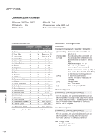
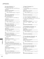
APPENDIX Communication Parameters A Baud rate : 9600 bps (UART) A Data length : 8 bits A Parity : None A Stop bit : 1 bit A Communication code : ASCII code A Use a crossed (reverse) cable. 110 APPENDIX Command Reference List Transmission / Receiving Protocol COMMAND COMMAND DATA 1 2 (Hexadecimal) Transmission [Command1][Command2][ ][Set ID][ ][Data][Cr] 01. Power k 02. Input Select k 03. Aspect Ratio k 04. Screen Mute k 05. Volume Mute k 06. Volume Control k 07. Contrast k 08. Brightness k a 0 ~1 * [Command 1] : First command to control the set. b Refer to p. 111 (j, k, m or x) c Refer to p. 111 * [Command 2] : Second command to control the set. d 0 ~1 * [Set ID] : You can adjust the set ID to choose e 0 ~1 desired monitor ID number in option menu. f 0 ~ 64 Adjustment range is 1 ~ 99. g 0 ~ 64 When selecting Set ID '0', every h 0 ~ 64 connected the set is controlled. 09. Colour k 10. Tint k 11. Sharpness k 12. OSD Select k 13. Remote control lock mode k 14. Balance k 15. Colour Temperature k i 0 ~ 64 Set ID is indicated as decimal (1~99) on j 0 ~ 64 menu and as Hexa decimal (0x0~0x63) k 0 ~ 64 on transmission/receiving protocol. l 0 ~1 * [DATA] : To transmit command data. Transmit 'FF' data to read status of m 0 ~1 command. t 0 ~ 64 * [Cr] : Carriage Return u 0 ~3 ASCII code '0x0D' 16. Red Adjustment k v 0 ~ 50 *[ ] : ASCII code 'space (0x20)' 17. Green Adjustment k 18. Blue Adjustment k w 0 ~ 50 $ 0 ~ 50 OK Acknowledgement 19. Abnormal Status k z 0 ~9 [Command2][ ][Set ID][ ][OK][Data][x] 20. ISM Method j 21. Low Power j 22. Auto Configure j p Refer to p. 113 * The set transmits ACK (acknowledgement) based on q 0 ~1 this format when receiving normal data. At this time, if u 1 the data is data read mode, it indicates present status 23. Channel Select Command m a Refer to p. 114 data. If the data is data write mode, it returns the 24. Send IR Code m c Key Code data of the PC computer. 25. Input select (Main) x b Refer to p. 114 Error Acknowledgement * When setting the 19 ~ 25, a menu doesn't display on screen. [Command2][ ][Set ID][ ][NG][Data][x] * The set transmits ACK (acknowledgement) based on this format when receiving abnormal data from non-viable functions or communication errors. Data 1: Illegal Code 2: not support function 3: Wait more time
-
 1
1 -
2
-
3
-
4
-
5
-
6
-
7
-
8
-
9
-
10
-
11
-
12
-
13
-
14
-
15
-
16
-
17
-
18
-
19
-
20
-
21
-
22
-
23
-
24
-
25
-
26
-
27
-
28
-
29
-
30
-
31
-
32
-
33
-
34
-
35
-
36
-
37
-
38
-
39
-
40
-
41
-
42
-
43
-
44
-
45
-
46
-
47
-
48
-
49
-
50
-
51
-
52
-
53
-
54
-
55
-
56
-
57
-
58
-
59
-
60
-
61
-
62
-
63
-
64
-
65
-
66
-
67
-
68
-
69
-
70
-
71
-
72
-
73
-
74
-
75
-
76
-
77
-
78
-
79
-
80
-
81
-
82
-
83
-
84
-
85
-
86
-
87
-
88
-
89
-
90
-
91
-
92
-
93
-
94
-
95
-
96
-
97
-
98
-
99
-
100
-
101
-
102
-
103
-
104
-
105
-
106
-
 107
107 -
 108
108 -
 109
109 -
 110
110 -
 111
111 -
 112
112 -
 113
113 -
 114
114 -
 115
115 -
 116
116 -
 117
117 -
118
-
119
-
120
 |
 |