LG 26LH1DC4 Owners Manual - Page 9
Back Panel Information, Except 42/50pc3
 |
View all LG 26LH1DC4 manuals
Add to My Manuals
Save this manual to your list of manuals |
Page 9 highlights
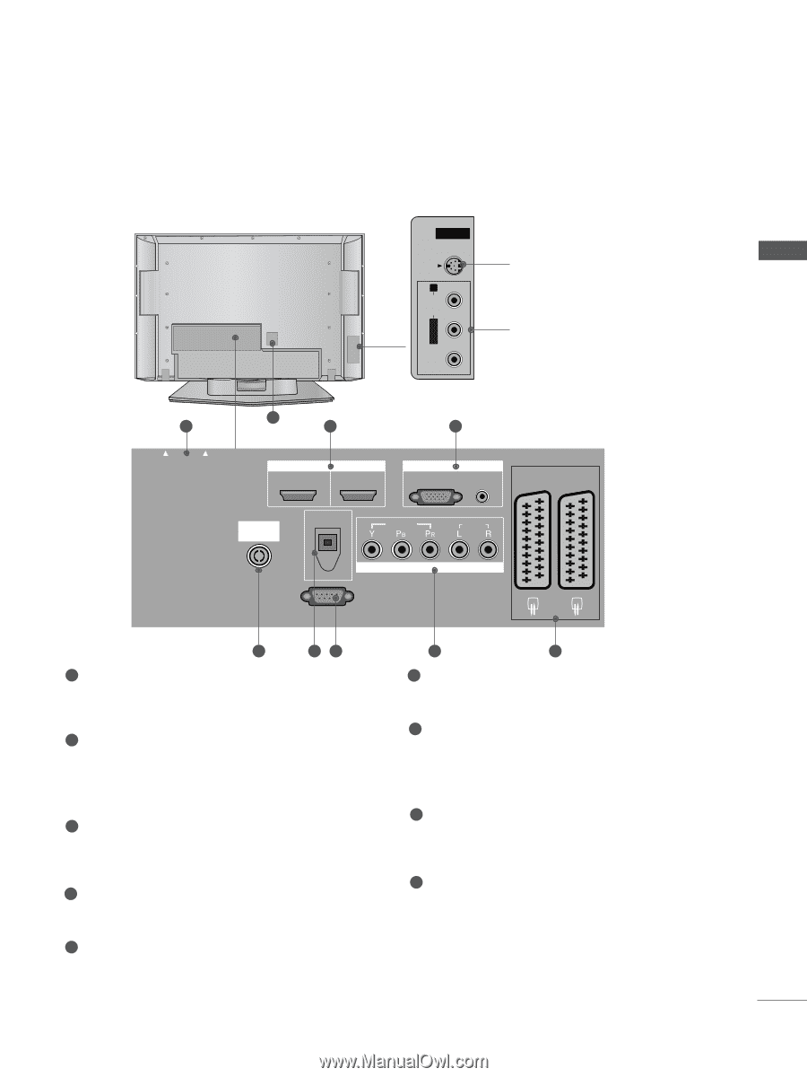
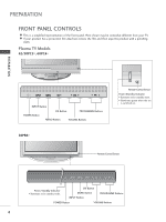
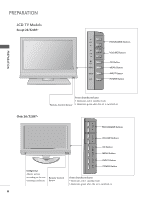
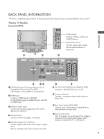
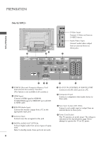
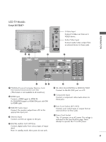
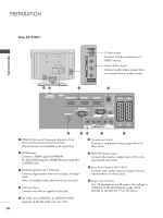
BACK PANEL INFORMATION A This is a simplified representation of the back panel. Here shown may be somewhat different from your TV. Plasma TV Models Except 42/50PC3* VIDEO R AUDIO L/MONO S-VIDEO VIDEO L/MONO AUDIO R S-VIDEO VIDEO L/MONO AUDIO R S-VIDEO AV IN 3 AV IN 3 AV IN 3 S-Video Input Connect S-Video out from an S-VIDEO device. Audio/Video Input Connect audio/video output from an external device to these jacks. PREPARATION A OT EJECT ANTENNA IN 9 1 2 3 PCMCIA CARD SLOT HDMI IN 1 2 VIDEO COMPONENT IN VIDEO AUDIO EJECT HDMI/DVIAIVN1 AV 1HADV M2 I IANV 2 RGB IN 1 2 RGB IN RGB AN(PTECN)NA IN AUDIO (RGB/DVI) AUDIO ANTENNA IN VARIABLE AUDIO OUT DIGITAL AUDIO OUT OPTICAL VIDEO AUDIO COMPONENT IN RS-232C IN RS-232C IN (CONTROL & SERVICE) AV 1 AV 2 4 56 1 PCMCIA (Personal Computer Memory Card International Association) Card Slot (This feature is not available in all countries.) 2 HDMI Input Connect a HDMI signal to HDMI IN. Or DVI(VIDEO)signal to HDMI/DVI port with DVI to HDMI cable. 3 RGB/DVI Audio Input Connect the monitor output from a PC to the appropriate input port. 4 Antenna Input Connect over-the-air signals to this jack. 5 DIGITAL AUDIO OUT OPTICAL Connect digital audio from various types of equipment. Note: In standby mode, these ports do not work. 7 8 6 RS-232C IN (CONTROL & SERVICE) PORT Connect to the RS-232C port on a PC. 7 Component Input Connect a component video/audio device to these jacks. 8 Euro Scart Socket (AV1/AV2) Connect scart socket input or output from an external device to these jacks. 9 Power Cord Socket This TV operates on an AC power. The voltage is indicated on the Specifications page. Never attempt to operate the TV on DC power. 7
-
 1
1 -
2
-
3
-
 4
4 -
 5
5 -
 6
6 -
 7
7 -
 8
8 -
 9
9 -
 10
10 -
 11
11 -
 12
12 -
 13
13 -
 14
14 -
15
-
16
-
17
-
18
-
19
-
20
-
21
-
22
-
23
-
24
-
25
-
26
-
27
-
28
-
29
-
30
-
31
-
32
-
33
-
34
-
35
-
36
-
37
-
38
-
39
-
40
-
41
-
42
-
43
-
44
-
45
-
46
-
47
-
48
-
49
-
50
-
51
-
52
-
53
-
54
-
55
-
56
-
57
-
58
-
59
-
60
-
61
-
62
-
63
-
64
-
65
-
66
-
67
-
68
-
69
-
70
-
71
-
72
-
73
-
74
-
75
-
76
-
77
-
78
-
79
-
80
-
81
-
82
-
83
-
84
-
85
-
86
-
87
-
88
-
89
-
90
-
91
-
92
-
93
-
94
-
95
-
96
-
97
-
98
-
99
-
100
-
101
-
102
-
103
-
104
-
105
-
106
-
107
-
108
-
109
-
110
-
111
-
112
-
113
-
114
-
115
-
116
-
117
-
118
-
119
-
120
 |
 |