LG 26LH1DC4 Owners Manual - Page 33
Digital Audio Out Setup
 |
View all LG 26LH1DC4 manuals
Add to My Manuals
Save this manual to your list of manuals |
Page 33 highlights
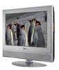
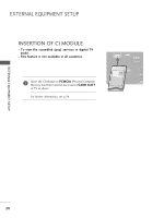
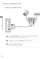
HDMI IN 2 AV 1 AV 2 When connecting with an S-Video cable VIDEO AUCDIOonnect the S-VIDEO output of the VCR to the S - 1 V I D E O input on the set. The picture quality is IN improved; compared to normal composite (RCA cable) input. 2 Connect the audio outputs of the VCR to the AUDIO input jacks on the set. S-VIDEO VIDEO L/MONO AUDIO R 3 Insert a video tape into the VCR and press PLAY on the VCR. (Refer to the VCR owner's manual.) 4 Select AV3 input source with using the INPUT button on the remote control. AV IN 3 S-VIDEO VIDEO L R ANT IN OUTPUT SWITCH ANT OUT 1 2 EXTERNAL EQUIPMENT SETUP ! NOTE G If both S-VIDEO and VIDEO sockets have been connected to the S-VHS VCR simultaneously, only the S-VIDEO can be received. S-VIDEO DIGITAL AUDIO OUT SETUP Send the TV's audio to external audio equipment via the Digital Audio Output (Optical) port. VIDEO L/MONO AUDIO R DIGITAL AUDIO OUT PCMCIA EJECT CARD SLOT 1 Connect one end of an optical cable to the TV Digital HDMI/DVI IN 1 HDMI IN 2 R RGB(PC AV Audio (Optical) Output port. AV IN 3 COMP 2 Connect the other end of the optical cable to the digi- tal audio (optical) input on the audio equipment. ANTENNA IN 1OPTICAL VIDEO AUDIO 3 Set the "TV Speaker option - Off" in the AUDIO menu. (Gp.85). See the external audio equipment instruction manual for operation. RS-232C IN (CONTROL & SERVICE) 2 CAUTION GDo not look into the optical output port. Looking at the laser beam may damage your vision. 31
-
 1
1 -
2
-
3
-
4
-
5
-
6
-
7
-
8
-
9
-
10
-
11
-
12
-
13
-
14
-
15
-
16
-
17
-
18
-
19
-
20
-
21
-
22
-
23
-
24
-
25
-
26
-
27
-
 28
28 -
 29
29 -
 30
30 -
 31
31 -
 32
32 -
 33
33 -
 34
34 -
 35
35 -
 36
36 -
 37
37 -
 38
38 -
39
-
40
-
41
-
42
-
43
-
44
-
45
-
46
-
47
-
48
-
49
-
50
-
51
-
52
-
53
-
54
-
55
-
56
-
57
-
58
-
59
-
60
-
61
-
62
-
63
-
64
-
65
-
66
-
67
-
68
-
69
-
70
-
71
-
72
-
73
-
74
-
75
-
76
-
77
-
78
-
79
-
80
-
81
-
82
-
83
-
84
-
85
-
86
-
87
-
88
-
89
-
90
-
91
-
92
-
93
-
94
-
95
-
96
-
97
-
98
-
99
-
100
-
101
-
102
-
103
-
104
-
105
-
106
-
107
-
108
-
109
-
110
-
111
-
112
-
113
-
114
-
115
-
116
-
117
-
118
-
119
-
120
 |
 |